31 0
Compare
control
INTy
DMAREQy
Compare
Update
compare
From counter
block 0
From counter
block 1
RTIUDCPy
RTICOMPy
31 0
=
+
RM46L852
www.ti.com
SPNS185 –SEPTEMBER 2012
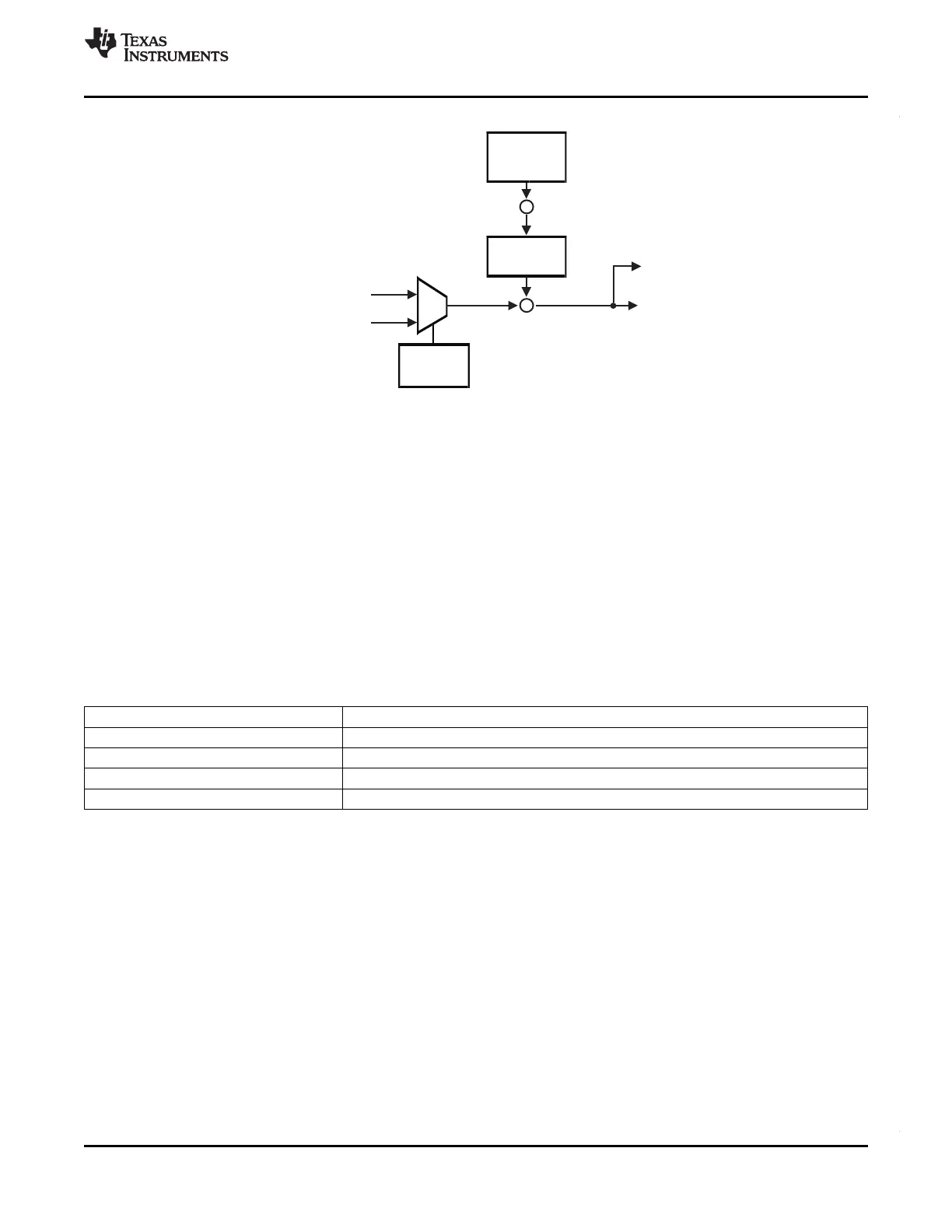
Figure 4-19. Compare Block Diagram
4.17.3 Clock Source Options
The RTI module uses the RTI1CLK clock domain for generating the RTI time bases.
The application can select the clock source for the RTI1CLK by configuring the RCLKSRC register in the
System module at address 0xFFFFFF50. The default source for RTI1CLK is VCLK.
For more information on clock sources refer to Table 4-8 and Table 4-13.
4.17.4 Network Time Synchronization Inputs
The RTI module supports 4 Network Time Unit (NTU) inputs that signal internal system events, and which
can be used to synchronize the time base used by the RTI module. On this device, these NTU inputs are
connected as shown below.
Table 4-34. Network Time Synchronization Inputs
NTU Input Source
0 Reserved
1 Reserved
2 PLL2 Clock output
3 EXTCLKIN1 clock input
Copyright © 2012, Texas Instruments Incorporated System Information and Electrical Specifications 103
Submit Documentation Feedback