EMIF_CLK
EMIF_BA[1:0]
EMIF_ADDR[12:0]
EMIF_DATA[15:0]
1
2 2
4
6
8
8
12
10
16
3
5
7
7
11
13
15
9
BASIC SDRAM
WRITE OPERATION
EMIF_CS[0]
EMIF_DQM[1:0]
EMIF_nRAS
EMIF_nCAS
EMIF_nWE
RM46L852
www.ti.com
SPNS185 –SEPTEMBER 2012
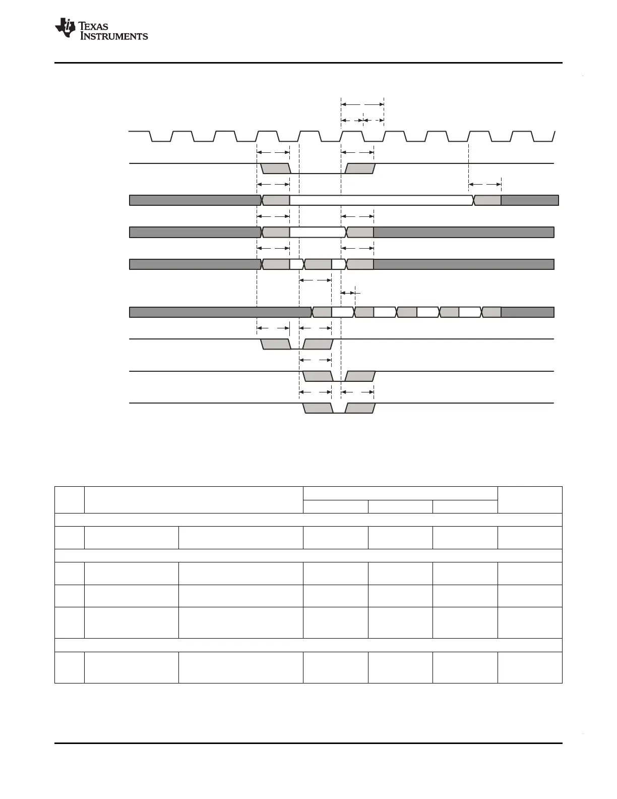
4.14.2.4 Write Timing (Synchronous RAM)
Figure 4-17. Basic SDRAM Write Operation
4.14.2.5 EMIF Asynchronous Memory Timing
Table 4-28. EMIF Asynchronous Memory Timing Requirements
NO. Value Unit
MIN NOM MAX
Reads and Writes
2 t
w(EM_WAIT)
Pulse duration, EMIFnWAIT 2E ns
assertion and deassertion
Reads
12 t
su(EMDV-EMOEH)
Setup time, EMIFDATA[15:0] 11 ns
valid before EMIFnOE high
13 t
h(EMOEH-EMDIV)
Hold time, EMIFDATA[15:0] 0.5 ns
valid after EMIFnOE high
14 t
su(EMOEL-EMWAIT)
Setup Time, EMIFnWAIT 4E+3 ns
asserted before end of Strobe
Phase
(1)
Writes
28 t
su(EMWEL-EMWAIT)
Setup Time, EMIFnWAIT 4E+3 ns
asserted before end of Strobe
Phase
(1)
(1) Setup before end of STROBE phase (if no extended wait states are inserted) by which EMIFnWAIT must be asserted to add extended
wait states. Figure Figure 4-13 and Figure Figure 4-15 describe EMIF transactions that include extended wait states inserted during the
STROBE phase. However, cycles inserted as part of this extended wait period should not be counted; the 4E requirement is to the start
of where the HOLD phase would begin if there were no extended wait cycles.
Copyright © 2012, Texas Instruments Incorporated System Information and Electrical Specifications 91
Submit Documentation Feedback