154
TMS320C6748
SPRS590G –JUNE 2009–REVISED JANUARY 2017
www.ti.com
Submit Documentation Feedback
Product Folder Links: TMS320C6748
Peripheral Information and Electrical Specifications Copyright © 2009–2017, Texas Instruments Incorporated
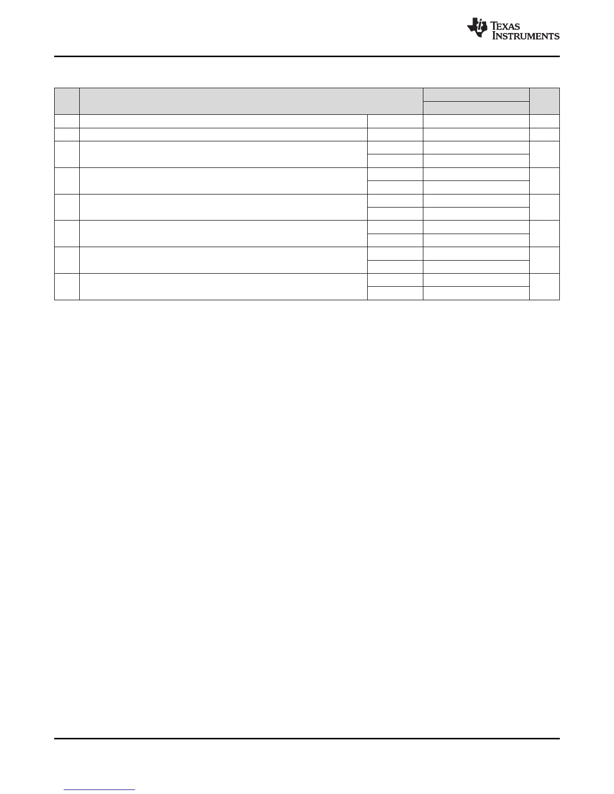
(1) CLKRP = CLKXP = FSRP = FSXP = 0. If polarity of any of the signals is inverted, then the timing references of that signal are also
inverted.
(2) P = ASYNC3 period in ns. For example, when the ASYNC clock domain is running at 100 MHz, use 10 ns.
(3) Use whichever value is greater. Minimum CLKR/X cycle times must be met, even when CLKR/X is generated by an internal clock
source. The minimum CLKR/X cycle times are based on internal logic speed; the maximum usable speed may be lower due to EDMA
limitations and AC timing requirements.
(4) This parameter applies to the maximum McBSP frequency. Operate serial clocks (CLKR/X) in the reasonable range of 40/60 duty cycle.
Table 6-58. Timing Requirements for McBSP0 [1.0V]
(1)
(see Figure 6-34)
NO.
1.0V
UNIT
MIN MAX
2 t
c(CKRX)
Cycle time, CLKR/X CLKR/X ext 2P or 26.6
(2)(3)
ns
3 t
w(CKRX)
Pulse duration, CLKR/X high or CLKR/X low CLKR/X ext P - 1
(4)
ns
5 t
su(FRH-CKRL)
Setup time, external FSR high before CLKR low
CLKR int 20
ns
CLKR ext 5
6 t
h(CKRL-FRH)
Hold time, external FSR high after CLKR low
CLKR int 6
ns
CLKR ext 3
7 t
su(DRV-CKRL)
Setup time, DR valid before CLKR low
CLKR int 20
ns
CLKR ext 5
8 t
h(CKRL-DRV)
Hold time, DR valid after CLKR low
CLKR int 3
ns
CLKR ext 3
10 t
su(FXH-CKXL)
Setup time, external FSX high before CLKX low
CLKX int 20
ns
CLKX ext 5
11 t
h(CKXL-FXH)
Hold time, external FSX high after CLKX low
CLKX int 6
ns
CLKX ext 3