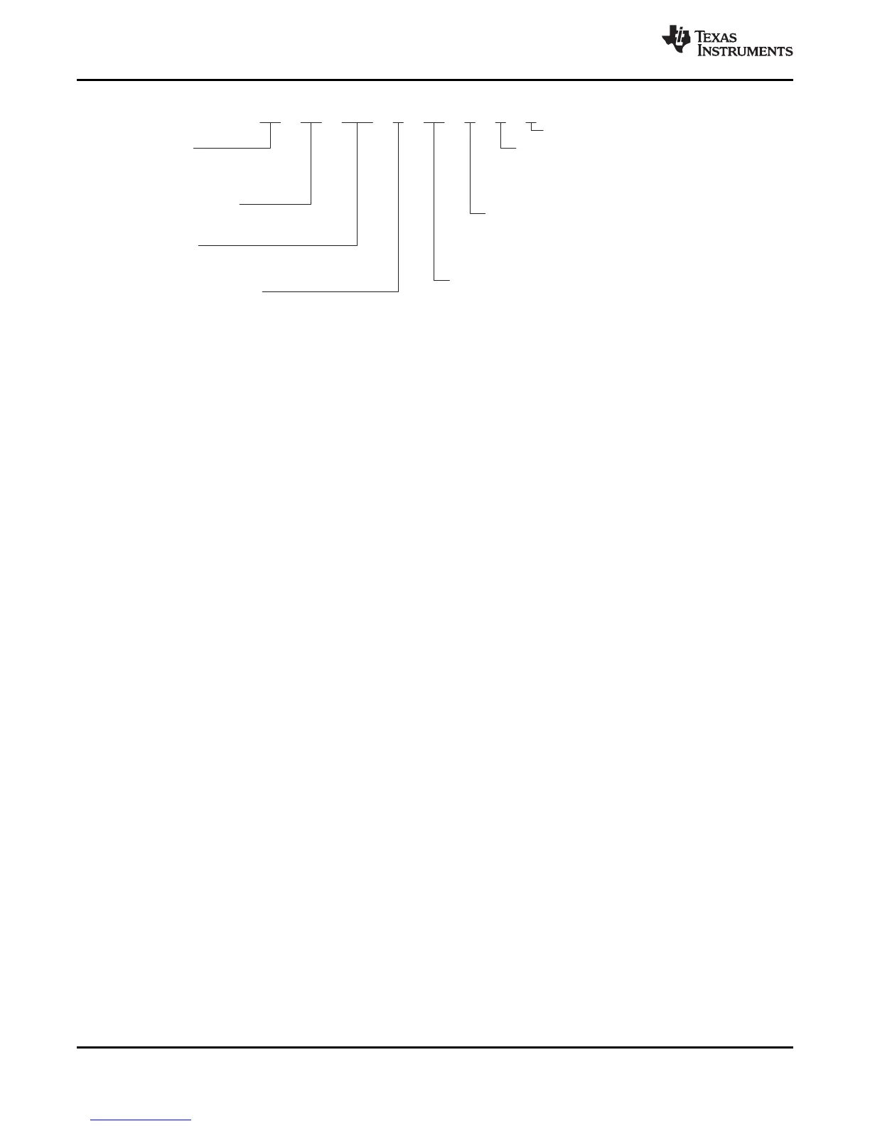
EasyManua.ls Logo

Texas Instruments TMS320C6748 User Manual

Texas Instruments TMS320C6748
274 pages
To Next Page IconTo Next Page
To Previous Page IconTo Previous Page
Page #264 background image
TMS
320
C6748
( )
ZWT
( ) ( )
PREFIX
TMX = Experimental Device
TMS = Qualified Device
DEVICE FAMILY
320 = TMS320â„¢ DSP Family
DEVICE
C6748
DEVICE SPEED RANGE
3 = 300 MHz (Revision 1.x)
TEMPERATURE RANGE (JUNCTION)
Blank = 0°C to 90°C, Commercial Grade
PACKAGE TYPE
(A)
361-Pin Plastic BGA, with Pb-free Soldered
Balls [Green], 0.65-mm Ball Pitch
ZCE =
SILICON REVISION
Blank = Revision 1.0
ZWT = 361-Pin Plastic BGA, with Pb-free Soldered
Balls [Green], 0.8-mm Ball Pitch
A = Revision 1.1
B = Revision 2.0
E = Revision 2.3
4 = 456 MHz (Revision 2.x)
3 = 375 MHz (Revision 2.x)
A = –40°C to 105°C, Extended Grade
D = –40°C to 90°C, Industrial Grade
(B)
E
Basic Secure Boot Enabled
264
TMS320C6748
SPRS590G –JUNE 2009–REVISED JANUARY 2017
www.ti.com
Submit Documentation Feedback
Product Folder Links: TMS320C6748
Device and Documentation Support Copyright © 2009–2017, Texas Instruments Incorporated
A. BGA = Ball Grid Array
B. Parts marked revision B are silicon revision 2.1 if '21' is marked on the package, and silicon revision 2.0 if there is no
'21' marking.
Figure 7-1. Device Nomenclature
7.2 Tools and Software
Software
Code Composer Studioâ„¢ Integrated Development Environment (IDE): including Editor
C/C++/Assembly Code Generation, and Debug plus additional development tools
Scalable, Real-Time Foundation Software (DSP/BIOSâ„¢) provides the basic run-time target software
needed to support any application.
Development Tools
Extended Development System (XDS â„¢) Emulator For a complete listing of development-support tools
for the device, visit the Texas Instruments web site on the Worldwide Web at
http://www.ti.com uniform resource locator (URL). For information on pricing and availability,
contact the nearest TI field sales office or authorized distributor.
7.3 Documentation Support
To receive notification of documentation updates, navigate to the device product folder on ti.com. In the
upper right corner, click on Alert me to register and receive a weekly digest of any product information that
has changed. For change details, review the revision history included in any revised document.
The current documentation that describes the DSP, related peripherals, and other technical collateral is
listed below.
User's Guides
SPRUG82 TMS320C674x DSP Cache User's Guide. Explains the fundamentals of memory caches
and describes how the two-level cache-based internal memory architecture in the
TMS320C674x digital signal processor (DSP) can be efficiently used in DSP applications.
Shows how to maintain coherence with external memory, how to use DMA to reduce
memory latencies, and how to optimize your code to improve cache efficiency. The internal
memory architecture in the C674x DSP is organized in a two-level hierarchy consisting of a
dedicated program cache (L1P) and a dedicated data cache (L1D) on the first level.
Accesses by the CPU to the these first level caches can complete without CPU pipeline
stalls. If the data requested by the CPU is not contained in cache, it is fetched from the next
lower memory level, L2 or external memory.
SPRUFE8 TMS320C674x DSP CPU and Instruction Set Reference Guide. Describes the CPU
architecture, pipeline, instruction set, and interrupts for the TMS320C674x digital signal
processors (DSPs). The C674x DSP is an enhancement of the C64x+ and C67x+ DSPs with
added functionality and an expanded instruction set.

Table of Contents

Question and Answer IconNeed help?

Do you have a question about the Texas Instruments TMS320C6748 and is the answer not in the manual?

Texas Instruments TMS320C6748 Specifications

General IconGeneral
BrandTexas Instruments
ModelTMS320C6748
CategoryControl Unit
LanguageEnglish

Summary

Device Overview

Features

Lists the key features of the TMS320C674x Fixed- and Floating-Point VLIW DSP.

Description

Functional Block Diagram

Device Comparison

Device Characteristics

Overview of C6748 hardware features, peripherals, on-chip memory, and package type.

Memory Map Summary

Pin Assignments

Pin Multiplexing Control

Terminal Functions

Device Reset, NMI and JTAG Terminal Functions

Details terminal functions for RESET, NMI, and JTAG signals.

External Memory Interface A (EMIFA) Terminal Functions

Details terminal functions for the External Memory Interface A.

DDR2/mDDR Controller Terminal Functions

Details terminal functions for the DDR2/mDDR Memory Controller.

Serial Peripheral Interface Modules (SPI) Terminal Functions

Details terminal functions for SPI0 and SPI1 modules.

Programmable Real-Time Unit (PRU) Terminal Functions

Details terminal functions for the Programmable Real-Time Unit.

Boot

Details boot mode selection terminal functions.

Inter-Integrated Circuit Modules(I2C0, I2C1) Terminal Functions

Details terminal functions for I2C0 and I2C1 modules.

Multichannel Audio Serial Ports (McASP) Terminal Functions

Details terminal functions for McASP modules.

Multichannel Buffered Serial Ports (McBSP) Terminal Functions

Details terminal functions for McBSP modules.

Universal Serial Bus Modules (USB0, USB1) Terminal Functions

Details terminal functions for USB0 and USB1 modules.

Ethernet Media Access Controller (EMAC) Terminal Functions

Details terminal functions for the EMAC module.

Multimedia Card/Secure Digital (MMC/SD) Terminal Functions

Details terminal functions for MMC/SD card interfaces.

Liquid Crystal Display Controller(LCD) Terminal Functions

Details terminal functions for the LCD controller.

Serial ATA Controller (SATA) Terminal Functions

Details terminal functions for the SATA controller.

Universal Host-Port Interface (UHPI) Terminal Functions

Details terminal functions for the UHPI interface.

Universal Parallel Port (uPP) Terminal Functions

Details terminal functions for the Universal Parallel Port.

Video Port Interface (VPIF) Terminal Functions

Details terminal functions for the Video Port Interface.

Supply and Ground Terminal Functions

Details terminal functions for supply and ground pins.

Device Configuration

Boot Modes

Describes the various boot modes supported by the internal DSP ROM bootloader.

Pullup/Pulldown Resistors

Specifications

Absolute Maximum Ratings Over Operating Junction Temperature Range

Specifies the absolute maximum ratings for voltage and temperature.

Handling Ratings

Details handling precautions, including ESD voltage ratings.

Recommended Operating Conditions

Specifies recommended operating conditions for supply voltage and junction temperature.

Electrical Characteristics Over Recommended Ranges of Supply Voltage and Operating Junction Temperature

Details electrical characteristics over recommended operating ranges.

Power Supplies

Power-On Sequence

Describes the required order for powering on the device's various supplies.

Reset

Power-On Reset (POR)

Explains the Power-On Reset behavior and its effects on device logic and pins.

Reset Electrical Data Timings

Crystal Oscillator or External Clock Input

Clock PLLs

Enhanced Direct Memory Access Controller (EDMA3)

EDMA3 Peripheral Register Descriptions

Describes the EDMA3 Channel Controller and Transfer Controller registers.

Interrupts

DSP Interrupts

Details the C674x DSP interrupt controller, prioritized interrupts, and registers.

Power and Sleep Controller (PSC)

Memory Protection Units

MMC / SD / SDIO (MMCSD0, MMCSD1)

Serial ATA Controller (SATA)

Multichannel Audio Serial Port (McASP)

Multichannel Buffered Serial Port (McBSP)

Serial Peripheral Interface Ports (SPI0, SPI1)

Inter-Integrated Circuit Serial Ports (I2C)

Universal Asynchronous Receiver/Transmitter (UART)

Universal Serial Bus OTG Controller (USB0) [USB2.0 OTG]

Universal Serial Bus Host Controller (USB1) [USB1.1 OHCI]

Ethernet Media Access Controller (EMAC)

LCD Controller (LCDC)

Host-Port Interface (UHPI)

Universal Parallel Port (uPP)

Video Port Interface (VPIF)

Enhanced Capture (eCAP) Peripheral

Real Time Clock (RTC)

General-Purpose Input/Output (GPIO)

Programmable Real-Time Unit Subsystem (PRUSS)

Emulation Logic

Electrostatic Discharge Caution

Related product manuals