ReceiveLogic
C lo ck/F ram e G e n era to r
StateMachine
ClockCheckand
Serializer0
Serializer1
Serializery
GIO
Control
DITRAM
384C
384U
Optional
Transm it
F o rm atte r
Receive
F o rm atte r
Transm it Logic
C lo ck/F ram e G e n era to r
StateMachine
McASP
Peripheral
Configuration
Bus
McASP
DMA Bus
(Dedicated)
AHCLKRx
ACLKRx
AFSRx
AMUTEINx
AMUTEx
AFSXx
ACLKXx
AHCLKXx
AXRx[0]
AXRx[1]
AXRx[y]
Pins
Function
ReceiveMasterClock
ReceiveBitClock
R e c eiv e Left/R ig h t C lo ck o r Fra m e S y n c
Transm it M a s te r C lo ck
Transm it B it C lo ck
Transm it Left/R ig h t C lo ck o r Fra m e S y n c
Transm it/Receiv e Se ria l D ata P in
Tra n sm it/R e c e iv e S erial D ata P in
Tra n sm it/R e c e iv e S erial D ata P in
ErrorDetection
TheMcASP DOESNOThavea
dedicated AMUTEINpin.
143
TMS320C6748
www.ti.com
SPRS590G –JUNE 2009–REVISED JANUARY 2017
Submit Documentation Feedback
Product Folder Links: TMS320C6748
Peripheral Information and Electrical SpecificationsCopyright © 2009–2017, Texas Instruments Incorporated
6.15 Multichannel Audio Serial Port (McASP)
The McASP serial port is specifically designed for multichannel audio applications. Its key features are:
• Flexible clock and frame sync generation logic and on-chip dividers
• Up to sixteen transmit or receive data pins and serializers
• Large number of serial data format options, including:
– TDM Frames with 2 to 32 time slots per frame (periodic) or 1 slot per frame (burst)
– Time slots of 8,12,16, 20, 24, 28, and 32 bits
– First bit delay 0, 1, or 2 clocks
– MSB or LSB first bit order
– Left- or right-aligned data words within time slots
• DIT Mode with 384-bit Channel Status and 384-bit User Data registers
• Extensive error checking and mute generation logic
• All unused pins GPIO-capable
• Transmit & Receive FIFO Buffers allow the McASP to operate at a higher sample rate by making it
more tolerant to DMA latency.
• Dynamic Adjustment of Clock Dividers
– Clock Divider Value may be changed without resetting the McASP
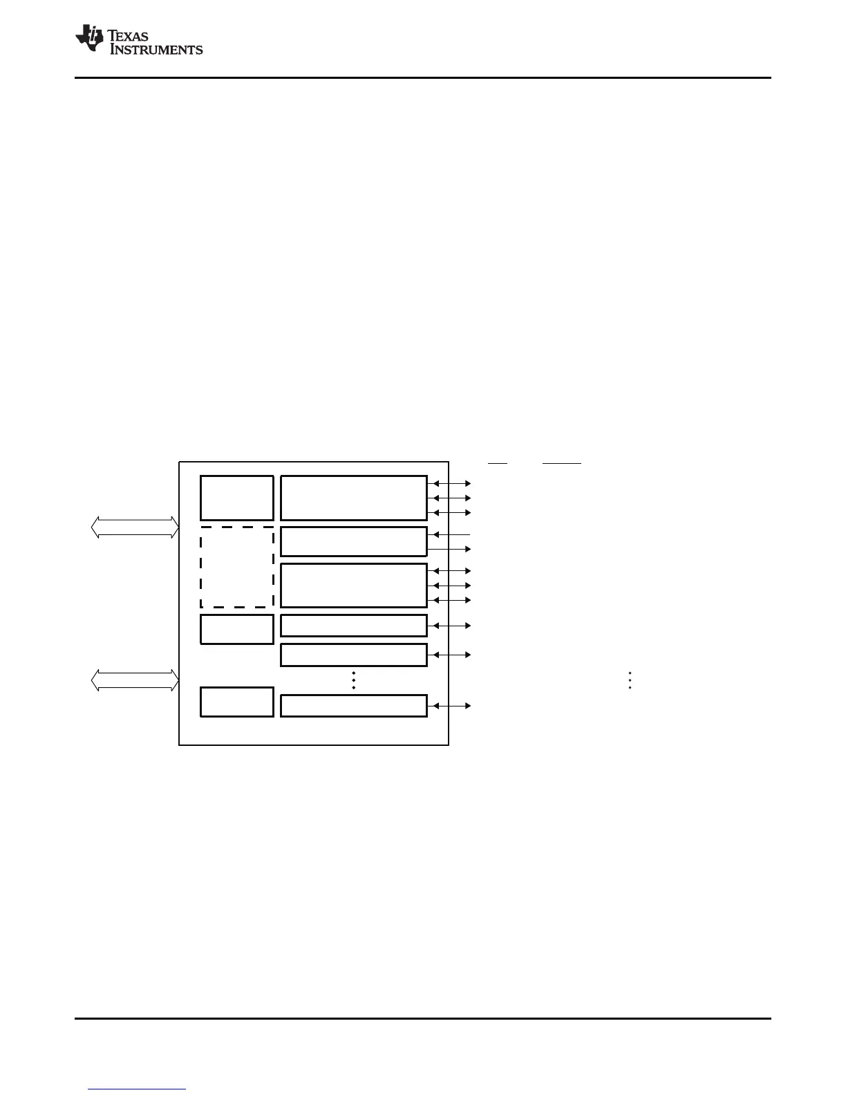
Figure 6-31. McASP Block Diagram