142
TMS320C6748
SPRS590G –JUNE 2009–REVISED JANUARY 2017
www.ti.com
Submit Documentation Feedback
Product Folder Links: TMS320C6748
Peripheral Information and Electrical Specifications Copyright © 2009–2017, Texas Instruments Incorporated
(1) Discrete clock frequency points are supported based on the PLL multiplier used in the SATA PHY.
Table 6-47 shows the requirements for the clock source.
Table 6-47. SATA Input Clock Source Requirements
PARAMETER MIN TYP MAX UNIT
Clock Frequency
(1)
75 375 MHz
Jitter 50 ps pk-pk
Duty Cycle 40 60 %
Rise/Fall Time 700 ps
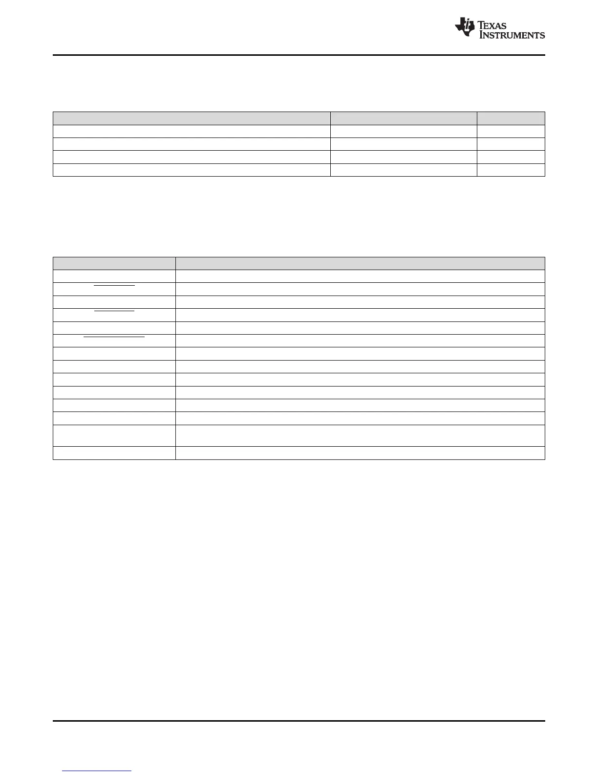
6.14.3 SATA Unused Signal Configuration
If the SATA interface is not used, the SATA signals should be configured as shown below.
Table 6-48. Unused SATA Signal Configuration
SATA Signal Name Configuration if SATA peripheral is not used
SATA_RXP No Connect
SATA_RXN No Connect
SATA_TXP No Connect
SATA_TXN No Connect
SATA_REFCLKP No Connect
SATA_REFCLKN No Connect
SATA_MPSWITCH May be used as GPIO or other peripheral function
SATA_CP_DET May be used as GPIO or other peripheral function
SATA_CP_POD May be used as GPIO or other peripheral function
SATA_LED May be used as GPIO or other peripheral function
SATA_REG No Connect
SATA_VDDR No Connect
SATA_VDD Prior to silicon revision 2.0, this supply must be connected to a static 1.2V nominal supply. For silicon
revision 2.0 and later, this supply may be left unconnected for additional power conservation.
SATA_VSS Vss