141
TMS320C6748
www.ti.com
SPRS590G –JUNE 2009–REVISED JANUARY 2017
Submit Documentation Feedback
Product Folder Links: TMS320C6748
Peripheral Information and Electrical SpecificationsCopyright © 2009–2017, Texas Instruments Incorporated
(1) Please refer to the Flip Chip Ball Grid Array Package Reference Guide (SPRU811) for device BGA pad size.
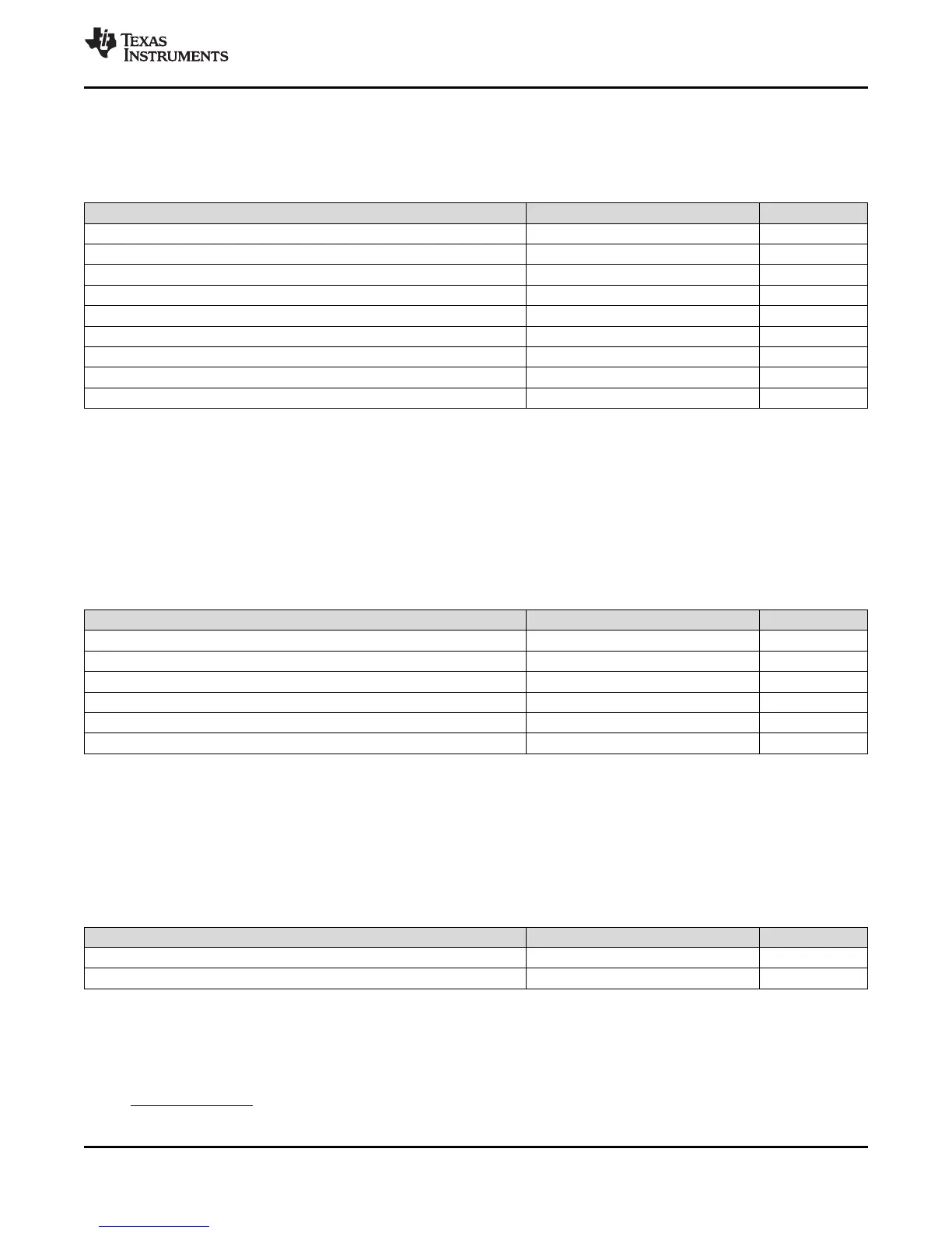
6.14.2.3 PCB Stackup Specifications
Table 6-44 shows the stackup and feature sizes required for SATA.
Table 6-44. SATA PCB Stackup Specifications
PARAMETER MIN TYP MAX UNIT
PCB Routing/Plane Layers 4 6 Layers
Signal Routing Layers 2 3 Layers
Number of ground plane cuts allowed within SATA routing region 0 Layers
Number of layers between SATA routing region and reference ground plane 0
PCB Routing Feature Size 4 Mils
PCB Trace Width w 4 Mils
PCB BGA escape via pad size 18 Mils
PCB BGA escape via hole size 8 Mils
Device BGA pad size
(1)
(1) The SATA_REFCLK(P/N) pins include an internal 100 Ohms differential termination
(2) Vias must be used in pairs with their distance minimized.
(3) DS is the differential spacing of the SATA traces.
6.14.2.4 Routing Specifications
The SATA data signal traces are edge-coupled and must be routed to achieve exactly 100 Ohms
differential impedance. This is impacted by trace width, trace spacing, distance between planes, and
dielectric material. Verify with a proper PCB manufacturing tool that the trace geometry for both data
signal pairs results in exactly 100 ohms differential impedance traces. Table 6-45 shows the routing
specifications for the data and REFCLK signals.
Table 6-45. SATA Routing Specifications
PARAMETER MIN TYP MAX UNIT
Device to SATA header trace length 7000 Mils
REFCLK trace length from oscillator to Device
(1)
2000 Mils
Number of stubs allowed on SATA traces 0 Stubs
TX/RX pair differential impedance 100 Ohms
Number of vias on each SATA trace 3 Vias
(2)
SATA differential pair to any other trace spacing 2*DS
(3)
(1) LxW, 10 mil units, i.e., a 0402 is a 40x20 mil surface mount capacitor.
(2) The physical size of the capacitor should be as small as possible.
6.14.2.5 Coupling Capacitors
AC coupling capacitors are required on the receive data pair as well as the REFCLK pair. Table 6-46
shows the requirements for these capacitors.
Table 6-46. SATA Bypass and Coupling Capacitors Requirements
PARAMETER MIN TYP MAX UNIT
SATA AC coupling capacitor value 0.3 10 12 nF
SATA AC coupling capacitor package size 0603 10 Mils
(1)(2)
6.14.2.6 SATA Interface Clock Source requirements
A high-quality, low-jitter differential clock source is required for the SATA PHY. The SATA interface
requires a LVDS differential clock source to be provided at signals SATA_REFCLKP and
SATA_REFCLKN. The clock source should be placed physically as close to the processor as possible.