SATA Interface(Processor)
SATA Connector
SATA_TXN
SATA_TXP
SATA_RXN
SATA_RXP
SATA_REFCLKN
SATA_REFCLKP
TX–
TX+
RX–
RX+
LVDS
Oscillator
CLK–
CLK+
SATA_REG
0.1uF
10nF
10nF
10nF
10nF
10nF
10nF
140
TMS320C6748
SPRS590G –JUNE 2009–REVISED JANUARY 2017
www.ti.com
Submit Documentation Feedback
Product Folder Links: TMS320C6748
Peripheral Information and Electrical Specifications Copyright © 2009–2017, Texas Instruments Incorporated
6.14.2 1. SATA Interface
This section provides the timing specification for the SATA interface as a PCB design and manufacturing
specification. The design rules constrain PCB trace length, PCB trace skew, signal integrity, cross-talk,
and signal timing. TI has performed the simulation and system design work to ensure the SATA interface
requirements are met.
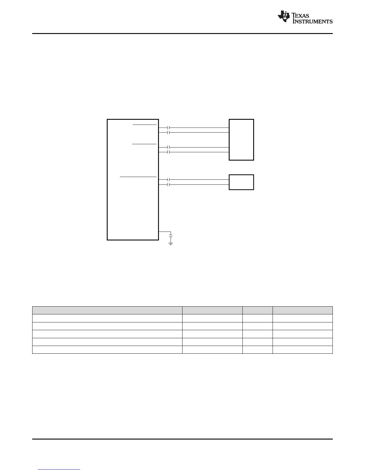
6.14.2.1 SATA Interface Schematic
Figure 6-30 shows the SATA interface schematic.
Figure 6-30. SATA Interface High Level Schematic
6.14.2.2 Compatible SATA Components and Modes
Table 6-43 shows the compatible SATA components and supported modes. Note that the only supported
configuration is an internal cable from the processor host to the SATA device.
Table 6-43. SATA Supported Modes
PARAMETER MIN MAX UNIT SUPPORTED
Transfer Rates 1.5 3.0 Gbps
eSATA No
xSATA No
Backplane No
Internal Cable Yes