267
TMS320C6748
www.ti.com
SPRS590G –JUNE 2009–REVISED JANUARY 2017
Submit Documentation Feedback
Product Folder Links: TMS320C6748
Mechanical Packaging and Orderable InformationCopyright © 2009–2017, Texas Instruments Incorporated
(1) These measurements were conducted in a JEDEC defined 2S2P system and will change based on environment as well as application.
For more information, see these EIA/JEDEC standards – EIA/JESD51-2, Integrated Circuits Thermal Test Method Environment
Conditions - Natural Convection (Still Air) and JESD51-7, High Effective Thermal Conductivity Test Board for Leaded Surface Mount
Packages. Power dissipation of 1W and ambient temp of 70C assumed. PCB with 2oz (70um) top and bottom copper thickness and
1.5oz (50um) inner copper thickness
(2) m/s = meters per second
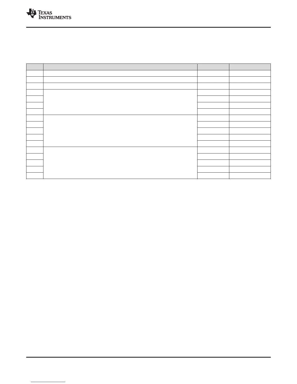
8.2 Thermal Data for ZWT Package
The following table shows the thermal resistance characteristics for the PBGA–ZWT mechanical package.
Table 8-2. Thermal Resistance Characteristics (PBGA Package) [ZWT]
NO. °C/W
(1)
AIR FLOW (m/s)
(2)
1 RΘ
JC
Junction-to-case 7.3 N/A
2 RΘ
JB
Junction-to-board 12.4 N /A
3 RΘ
JA
Junction-to-free air 23.7 0.00
4
RΘ
JMA
Junction-to-moving air
21.0 0.50
5 20.1 1.00
6 19.3 2.00
7 18.4 4.00
8
Psi
JT
Junction-to-package top
0.2 0.00
9 0.3 0.50
10 0.3 1.00
11 0.4 2.00
12 0.5 4.00
13
Psi
JB
Junction-to-board
12.3 0.00
14 12.2 0.50
15 12.1 1.00
16 12.0 2.00
17 11.9 4.00
8.3 Packaging Information
The following packaging information and addendum reflect the most current data available for the
designated device(s). This data is subject to change without notice and without revision of this document.