C
2
C
1
X
1
OSCOUT
OSCIN
OSCV
SS
ClockInput
toPLL
86
TMS320C6748
SPRS590G –JUNE 2009–REVISED JANUARY 2017
www.ti.com
Submit Documentation Feedback
Product Folder Links: TMS320C6748
Peripheral Information and Electrical Specifications Copyright © 2009–2017, Texas Instruments Incorporated
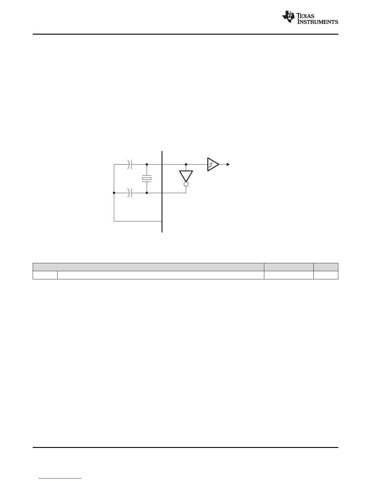
6.5 Crystal Oscillator or External Clock Input
The device includes two choices to provide an external clock input, which is fed to the on-chip PLLs to
generate
high-frequency system clocks. These options are illustrated in Figure 6-6 and Figure 6-7. For input clock
frequencies between 12 and 20 MHz, a crystal with 80 ohm max ESR is recommended. For input clock
frequencies between 20 and 30 MHz, a crystal with 60 ohm max ESR is recommended. Typical load
capacitance values are 10-20 pF, where the load capacitance is the series combination of C1 and C2.
The CLKMODE bit in the PLLCTL register must be 0 to use the on-chip oscillator. If CLKMODE is set to 1,
the internal oscillator is disabled.
Figure 6-6 illustrates the option that uses on-chip 1.2V oscillator with external crystal circuit. Figure 6-7
illustrates the option that uses an external 1.2V clock input.
Figure 6-6. On-Chip Oscillator
Table 6-2. Oscillator Timing Requirements
PARAMETER MIN MAX UNIT
f
osc
Oscillator frequency range (OSCIN/OSCOUT) 12 30 MHz