260
TMS320C6748
SPRS590G –JUNE 2009–REVISED JANUARY 2017
www.ti.com
Submit Documentation Feedback
Product Folder Links: TMS320C6748
Peripheral Information and Electrical Specifications Copyright © 2009–2017, Texas Instruments Incorporated
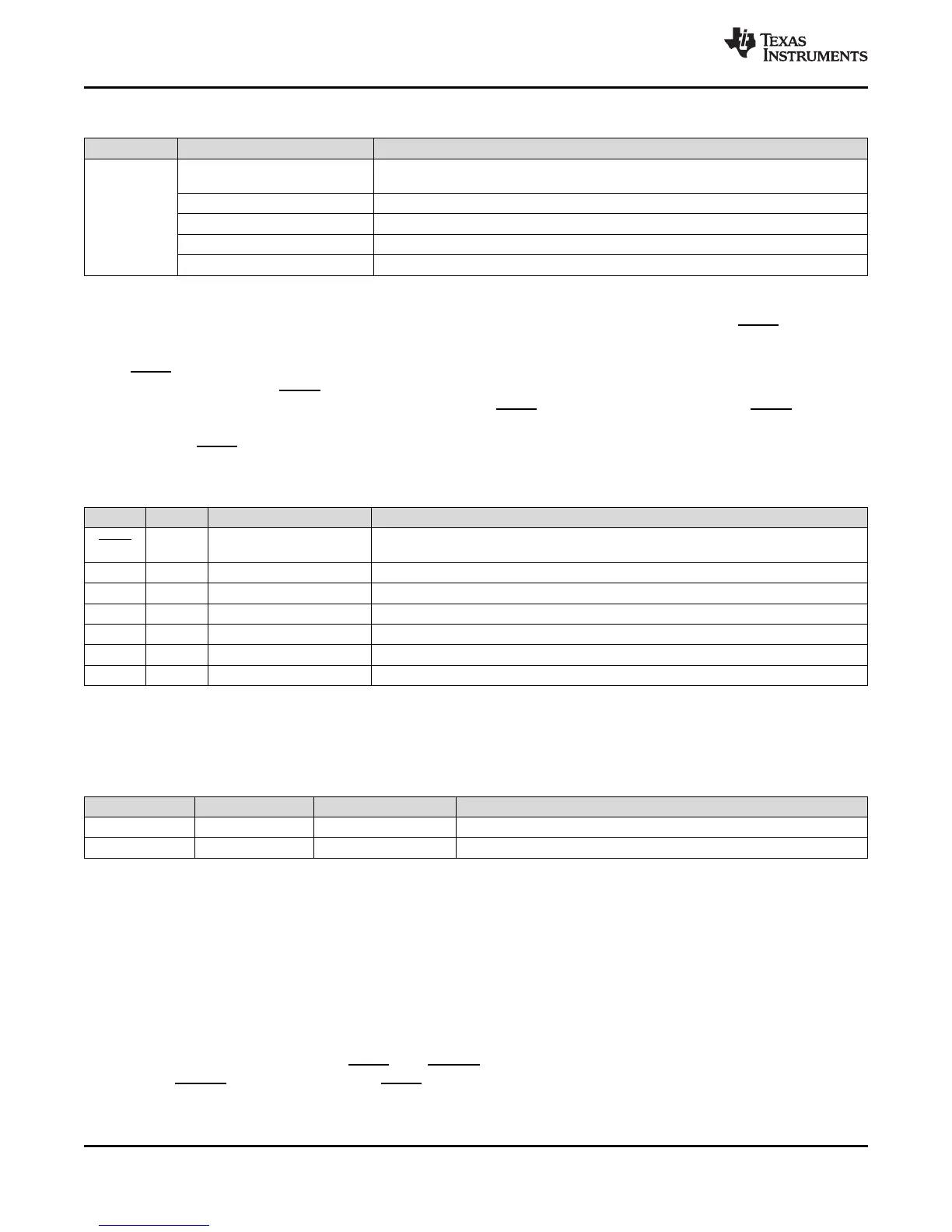
Table 6-142. DSP Debug Features (continued)
Category Hardware Feature Availability
Analysis
Watch point
Up to 4 watch points, which are shared with HWBPs, and can also be used as 2 watch
points with data (32 bits)
Watch point with Data Up to 2, Which can also be used as 4 watch points.
Counters/timers 1x64-bits (cycle only) + 2x32-bits (water mark counters)
External Event Trigger In 1
External Event Trigger Out 1
6.34.1 JTAG Port Description
The device target debug interface uses the five standard IEEE 1149.1(JTAG) signals (TRST, TCK, TMS,
TDI, and TDO).
TRST holds the debug and boundary scan logic in reset (normal DSP operation) when pulled low (its
default state). Since TRST has an internal pull-down resistor, this ensures that at power up the device
functions in its normal (non-test) operation mode if TRST is not connected. Otherwise, TRST should be
driven inactive by the emulator or boundary scan controller. Boundary scan test cannot be performed
while the TRST pin is pulled low.
Table 6-143. JTAG Port Description
PIN TYPE NAME DESCRIPTION
TRST I Test Logic Reset
When asserted (active low) causes all test and debug logic in the device to be reset
along with the IEEE 1149.1 interface
TCK I Test Clock This is the test clock used to drive an IEEE 1149.1 TAP state machine and logic.
TMS I Test Mode Select Directs the next state of the IEEE 1149.1 test access port state machine
TDI I Test Data Input Scan data input to the device
TDO O Test Data Output Scan data output of the device
EMU0 I/O Emulation 0 Channel 0 trigger + HSRTDX
EMU1 I/O Emulation 1 Channel 1 trigger + HSRTDX
6.34.2 Scan Chain Configuration Parameters
Table 6-144 shows the TAP configuration details required to configure the router/emulator for this device.
Table 6-144. JTAG Port Description
Router Port ID Default TAP TAP Name Tap IR Length
17 No C674x 38
19 No ETB 4
(1) IEEE Standard 1149.1-1990 Standard-Test-Access Port and Boundary Scan Architecture.
The router is revision C and has a 6-bit IR length.
6.34.3 Initial Scan Chain Configuration
The first level of debug interface that sees the scan controller is the TAP router module. The debugger
can configure the TAP router for serially linking up to 16 TAP controllers or individually scanning one of
the TAP controllers without disrupting the IR state of the other TAPs.
6.34.4 IEEE 1149.1 JTAG
The JTAG
(1)
interface is used for BSDL testing and emulation of the device.
The device requires that both TRST and RESET be asserted upon power up to be properly initialized.
While RESET initializes the device, TRST initializes the device's emulation logic. Both resets are required
for proper operation.