OSCIN
RESET
RESETOUT
Boot Pins
Config
Power
Supplies
Ramping
Power Supplies Stable
Clock Source Stable
1
2
3
4
TRST
84
TMS320C6748
SPRS590G –JUNE 2009–REVISED JANUARY 2017
www.ti.com
Submit Documentation Feedback
Product Folder Links: TMS320C6748
Peripheral Information and Electrical Specifications Copyright © 2009–2017, Texas Instruments Incorporated
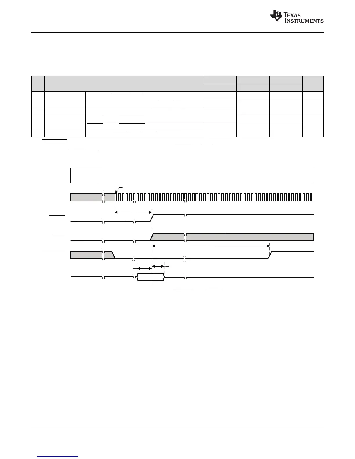
(1) RESETOUT is multiplexed with other pin functions. See the Terminal Functions table, Table 3-5 for details.
(2) For power-on reset (POR), the reset timings in this table refer to RESET and TRST together. For warm reset, the reset timings in this
table refer to RESET only (TRST is held high).
(3) OSCIN cycles.
6.4.3 Reset Electrical Data Timings
Table 6-1 assumes testing over the recommended operating conditions.
Table 6-1. Reset Timing Requirements (
(1)
,
(2)
)
NO.
1.3V, 1.2V 1.1V 1.0V
UNIT
MIN MAX MIN MAX MIN MAX
1 t
w(RSTL)
Pulse width, RESET/TRST low 100 100 100 ns
2 t
su(BPV-RSTH)
Setup time, boot pins valid before RESET/TRST high 20 20 20 ns
3 t
h(RSTH-BPV)
Hold time, boot pins valid after RESET/TRST high 20 20 20 ns
4
t
d(RSTH-
RESETOUTH)
RESET high to RESETOUT high; Warm reset 4096 4096 4096 cycles
(3)
RESET high to RESETOUT high; Power-on Reset 6169 6169 6169
5 t
d(RSTL-RESETOUTL)
Delay time, RESET/TRST low to RESETOUT low 14 16 20 ns
Figure 6-4. Power-On Reset (RESET and TRST active) Timing