91
TMS320C6748
www.ti.com
SPRS590G –JUNE 2009–REVISED JANUARY 2017
Submit Documentation Feedback
Product Folder Links: TMS320C6748
Peripheral Information and Electrical SpecificationsCopyright © 2009–2017, Texas Instruments Incorporated
Voltage scaling is enabled from outside the device by controlling an external voltage regulator. The
processor may communicate with the regulator using GPIOs, I2C or some other interface. When switching
between voltage-frequency operating points, the voltage must always support the desired frequency.
When moving from a high-performance operating point to a lower performance operating point, the
frequency should be lowered first followed by the voltage. When moving from a low-performance operating
point to a higher performance operating point, the voltage should be raised first followed by the frequency.
Voltage operating points refer to the CVdd voltage at that point. Other static supplies must be maintained
at their nominal voltages at all operating points.
The maximum voltage slew rate for CVdd supply changes is 1 mV/us.
For additional information on power management solutions from TI for this processor, follow the Power
Management link in the Product Folder on www.ti.com for this processor.
The processor supports multiple clock domains some of which have clock ratio requirements to each
other. SYSCLK1:SYSCLK2:SYSCLK4:SYSCLK6 are synchronous to each other and the SYSCLKn
dividers must always be configured such that the ratio between these domains is 1:2:4:1. The ASYNC and
ASYNC3 clock domains are asynchronous to the other clock domains and have no specific ratio
requirement.
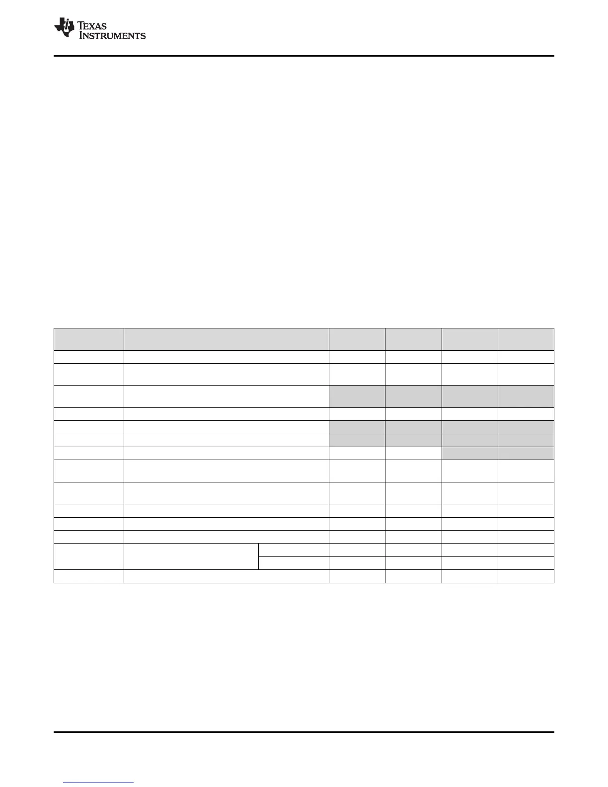
Table 6-5 summarizes the maximum internal clock frequencies at each of the voltage operating points.
Table 6-5. Maximum Internal Clock Frequencies at Each Voltage Operating Point
CLOCK
SOURCE
CLOCK DOMAIN 1.3V NOM 1.2V NOM 1.1V NOM 1.0V NOM
PLL0_SYSCLK1 DSP subsystem 456 MHz 375 MHz 200 MHz 100 MHz
PLL0_SYSCLK2
SYSCLK2 clock domain peripherals and optional clock
source for ASYNC3 clock domain peripherals
228 MHz 187.5 MHz 100 MHz 50 MHz
PLL0_SYSCLK3
Optional clock for ASYNC1 clock domain
(See ASYNC1 row)
PLL0_SYSCLK4 SYSCLK4 domain peripherals 114 MHz 93.75 MHz 50 MHz 25 MHz
PLL0_SYSCLK5 Not used on this processor - - - -
PLL0_SYSCLK6 Not used on this processor - - - -
PLL0_SYSCLK7 Optional 50 MHz clock source for EMAC RMII interface 50 MHz 50 MHz - -
PLL1_SYSCLK1
DDR2/mDDR Interface clock source
(memory interface clock is one-half of the value shown)
312 MHz 312 MHz 300 MHz 266 MHz
PLL1_SYSCLK2
Optional clock source for ASYNC3 clock domain
peripherals
152 MHz 150 MHz 100 MHz 75 MHz
PLL1_SYSCLK3 Alternate clock source input to PLL Controller 0 75 MHz 75 MHz 75 MHz 75 MHz
McASP AUXCLK Bypass clock source for the McASP 50 MHz 50 MHz 50 MHz 50 MHz
PLL0_AUXCLK Bypass clock source for the USB0 and USB1 48 MHz 48 MHz 48 MHz 48 MHz
ASYNC1 ASYNC Clock Domain (EMIFA)
Async Mode 148 MHz 148 MHz 75 MHz 50 MHz
SDRAM Mode 100 MHz 100 MHz 66.6 MHz 50 MHz
ASYNC2 ASYNC2 Clock Domain (multiple peripherals) 50 MHz 50 MHz 50 MHz 50 MHz
Some interfaces have specific limitations on supported modes/speeds at each operating point. See the
corresponding peripheral sections of this document for more information.
TI provides software components (called the Power Manager) to perform DVFS and abstract the task from
the user. The Power Manager controls changing operating points (both frequency and voltage) and
handles the related tasks involved such as informing/controlling peripherals to provide graceful transitions
between operating points. The Power Manager is bundled as a component of DSP/BIOS.