REPLACEMENT PROCEDURES 5-6 Manual 0-2957
10. Connect wires per the chart.
Input Diode To Main PCB Input Diode To Main PCB
E5 E1 E5 E1
E13 E2
E18 E3
E6, E8 E7 E6, E8 E7
E14, E16 E15 E14, E16 E15
400V, 415V, 460V,
600V Units
208/230V Units
CutMaster 81 Input Diode Connections
E13, E18 E2
For IGBTs:
a. Apply a round thermal pad to the heatsink
with a small piece of light-duty tape. The tape
must cover no more than 1/8" (3 mm) of the
edge of the thermal pad. Use the screw hole
in the heatsink as a guide to position the board.
Washer
Screw
Output Diode
or IGBT
Round
Thermal Pad
Art # A-03702
Tape
Tape
b. Secure replacement board(s) with the screw
removed previously. Ensure that the washer
is under the head of the screw.
9. Torque screw(s) to 17 in-lb. (1.9 Nm).
NOTE
Failure to torque properly will cause component
damage.
10. Connect wires per the chart.
IGBT A
Connector
To Main PCB
Connector
IGBT B
Connector
To Main PCB
Connector
J3 J25 J3 J31
J7 J30 J7 J26
E9, E11 E10 E9, E11 E27
E19, E21 E20 E19, E21 E30
E12, E17 E4 E12, E17 E23
IGBT A IGBT B
CutMaster 81 IGBT Connections
11. Stand the unit upright; reinstall the cover.
E. Main Power PC Board Replacement
Follow the antistatic procedures in subsection 5.02.
1. Remove cover per subsection 5.04-A.
2. Remove the Logic PC Board per subsection 5.06-C.
3. Disconnect all wire and cable connections to the
Main PC Board. Refer to the Main PC Board Wir-
ing Diagrams in the Appendix Pages if necessary.
Straighten the connections to the smaller PC
Boards to be perpendicular to the Main PC Board.
5. Remove the two long Transformer screws secur-
ing the Transformer to the Center Chassis.
6. Remove the other screws securing the PC Board
to the Center Chassis.
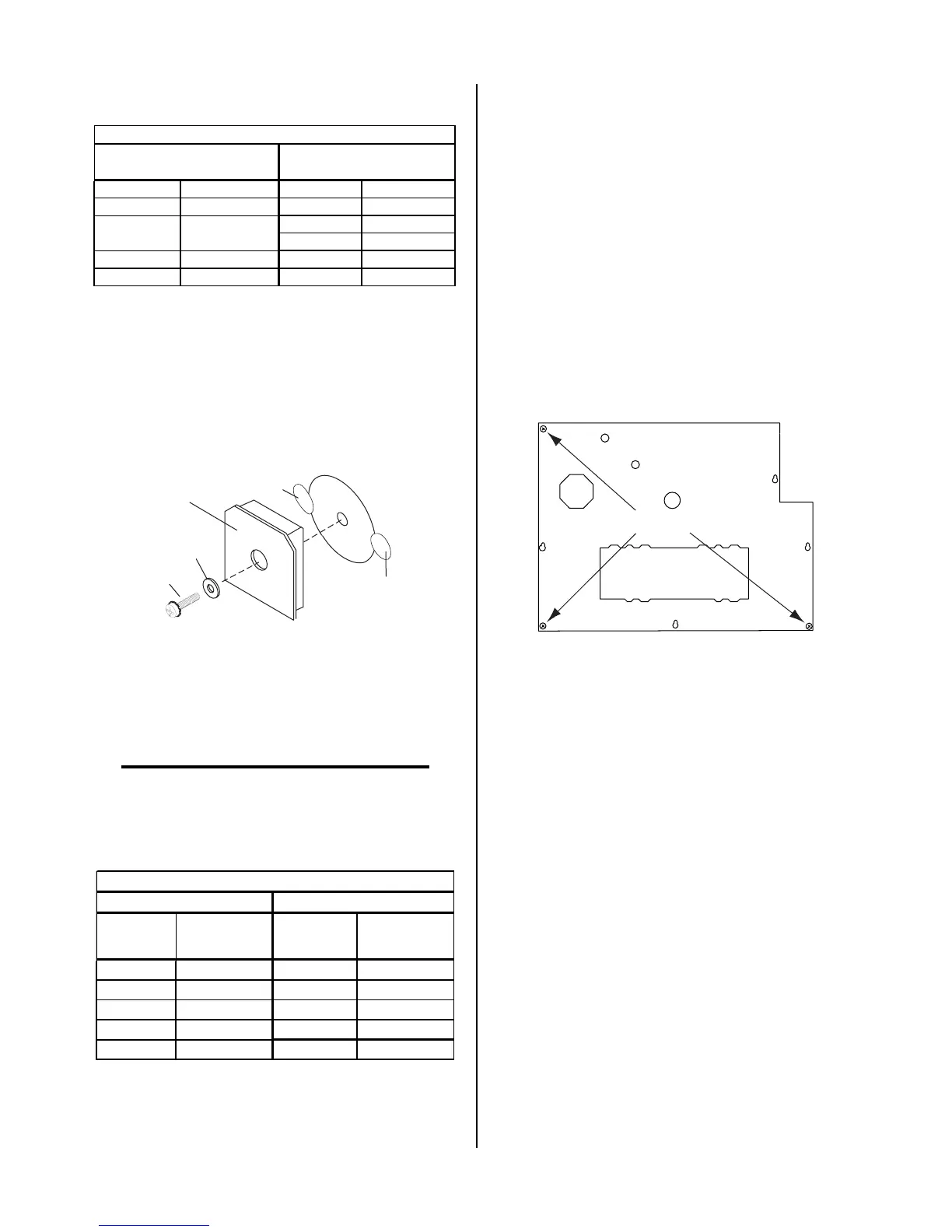
Art # A-03165
Screw locations
7. Carefully remove the original PC Board from the
unit.
8. Transfer the Logic PC Board standoffs to the re-
placement Main PC Board.
9. Install the replacement PC Board by reversing the
steps above. It may be easier to install the PC
Board if the Power Supply is turned on its right
side first. Refer to the charts in subsection 5.06-D
for input diode and IGBT wiring connection
points.
F. EMI Filter Replacement (CE Units only)
1. Label the input power cable connections and the
cable connections to the main input contactor.
2. Disconnect all wire and cable connections to the
EMI Filter.
3. Remove the hardware securing the EMI Filter.
This hardware passes upward through the base
of the power supply.
4. Put the replacement EMI Filter in position and
secure it with the hardware removed in Step 3.