cutmaster 102
SERVICE 5-24 Manual 0-4998
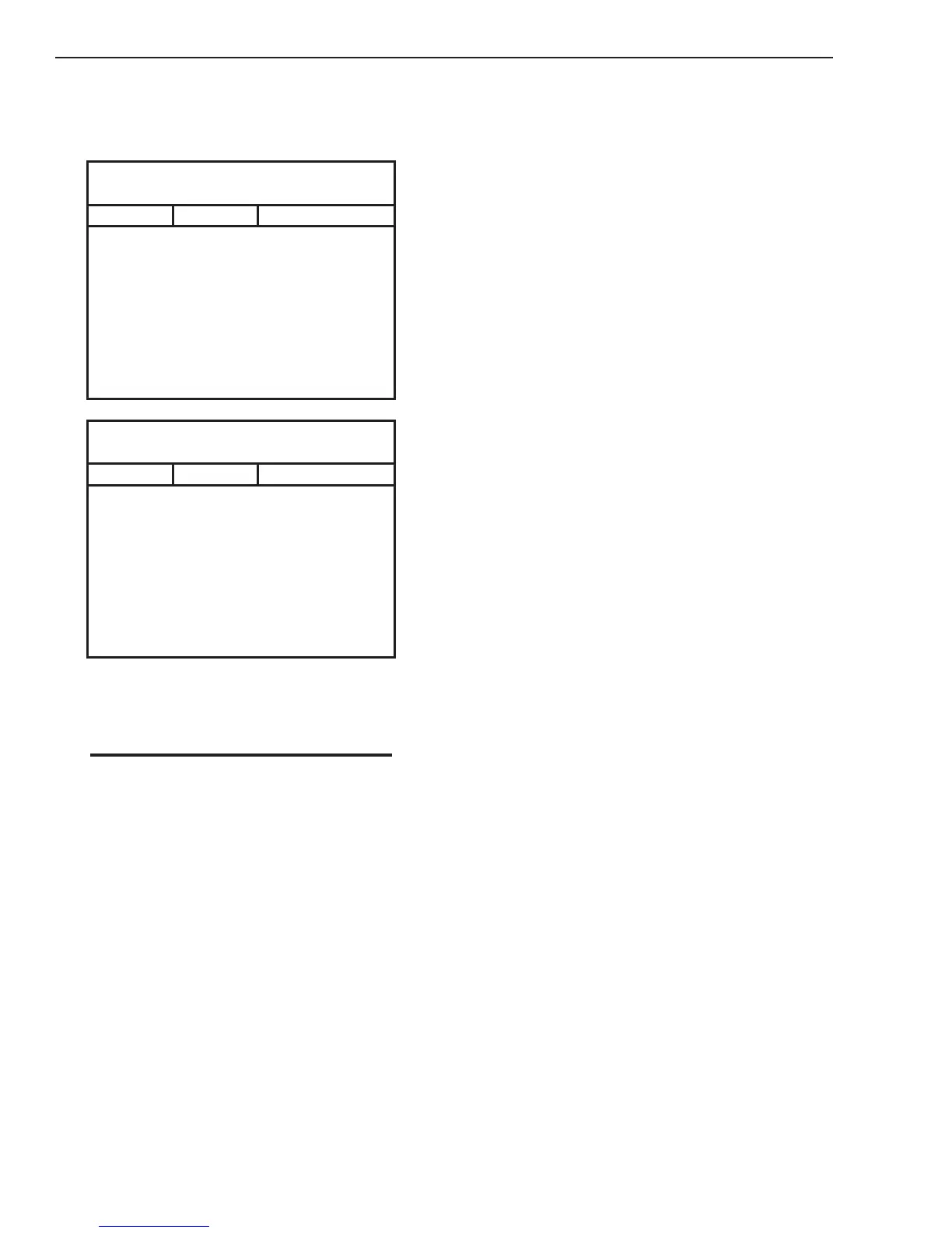
N. PCB 5 IGBT Test. ( With PCB 2 removed
from unit)
1. Using an ohmmeter perform the following
checks::
PCB 5 - Q1
Test points located on PCB 5
Meter (+) Meter (-) Indication
PRI 1 PMTH 1 Forward Biased Diode
PRI 1 PMTH 2 Reverse Biased Diode
PMTH 1 PRI 1 Reverse Biased Diode
PMTH 2 PRI 1 Forward Biased Diode
PRI 2 PMTH 1 Forward Biased Diode
PRI 2 PMTH 2 Reverse Biased Diode
PMTH 1 PRI 2 Reverse Biased Diode
PMTH 2 PRI 2 Forward Biased Diode
PCB 5 – Q2
Test points located on PCB 5
Meter (+) Meter (-) Indication
PRI 4 PMTH 3 Forward Biased Diode
PRI 4 PMTH 4 Reverse Biased Diode
PMTH 3 PRI 4 Reverse Biased Diode
PMTH 4 PRI 4 Forward Biased Diode
PRI 3 PMTH 4 Forward Biased Diode
PRI 3 PMTH 3 Reverse Biased Diode
PMTH 4 PRI 3 Reverse Biased Diode
PMTH 3 PRI 3 Forward Biased Diode
2. If the test reveals a failed component, replace
40Amp PCB 5.
NOTE
Many of the signals listed in the PCB information
to follow will be low voltage signals that will be
in one of two states: +12VDC (High) or 0VDC
(Low) with respect to pcb common.. When a signal
name is preceded by the “/” mark, it denotes that
the signal is an active low. For example:
/OVERTEMP – This signal is normally High but
when an over temperature fault exists, this line
will change state to a Low.