CUTMASTER 58
Manual 0-5544 INTRODUCTION
2T-3
A-00002
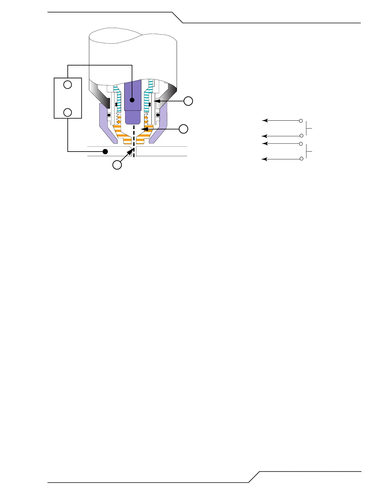
Workpiece
Power
Supply
+
_
B
A
Typical Torch Head Detail
By forcing the plasma gas and electric arc through a
small orice, the torch delivers a high concentration of
heat to a small area. The sti, constricted plasma arc is
shown in Zone C. Direct current (DC) straight polarity
is used for plasma cutting, as shown in the illustration.
Zone A channels a secondary gas that cools the torch.
This gas also assists the high velocity plasma gas in
blowing the molten metal out of the cut allowing for a
fast, slag - free cut.
B. Gas Distribution
The single gas used is internally split into plasma and
secondary gases.
The plasma gas ows into the torch through the nega-
tive lead, through the starter cartridge, around the elec-
trode, and out through the tip orice.
The secondary gas ows down around the outside of
the torch starter cartridge, and out between the tip and
shield cup around the plasma arc.
C. Pilot Arc
When the torch is started a pilot arc is established be-
tween the electrode and cutting or gouging tip. This
pilot arc creates a path for the main arc to transfer to
the work.
D. Main Cutting Arc
DC power is also used for the main cutting arc. The
negative output is connected to the torch electrode
through the torch lead. The positive output is con-
nected to the workpiece via the work cable and to the
torch through a pilot wire.
E. Parts - In - Place (PIP)
The torch includes a 'Parts - In - Place' (PIP) circuit. When
the shield cup is properly installed, it closes a switch. The
torch will not operate if this switch is open.
Torch Trigge
PIP Switch
Shield Cup
To Control
Cable Wiring
Torch Switch
Parts - In - Place Circuit Diagram for Hand Torch