cutmaster 82
SERVICE 5-22 Manual 0-4980
D5
D3
D2
D4
D6
D7
D8
D9
D10
D11
D12
D13
D14
D1
TP3
TP4
TP1
J1*
TP7
TP6
T
P5
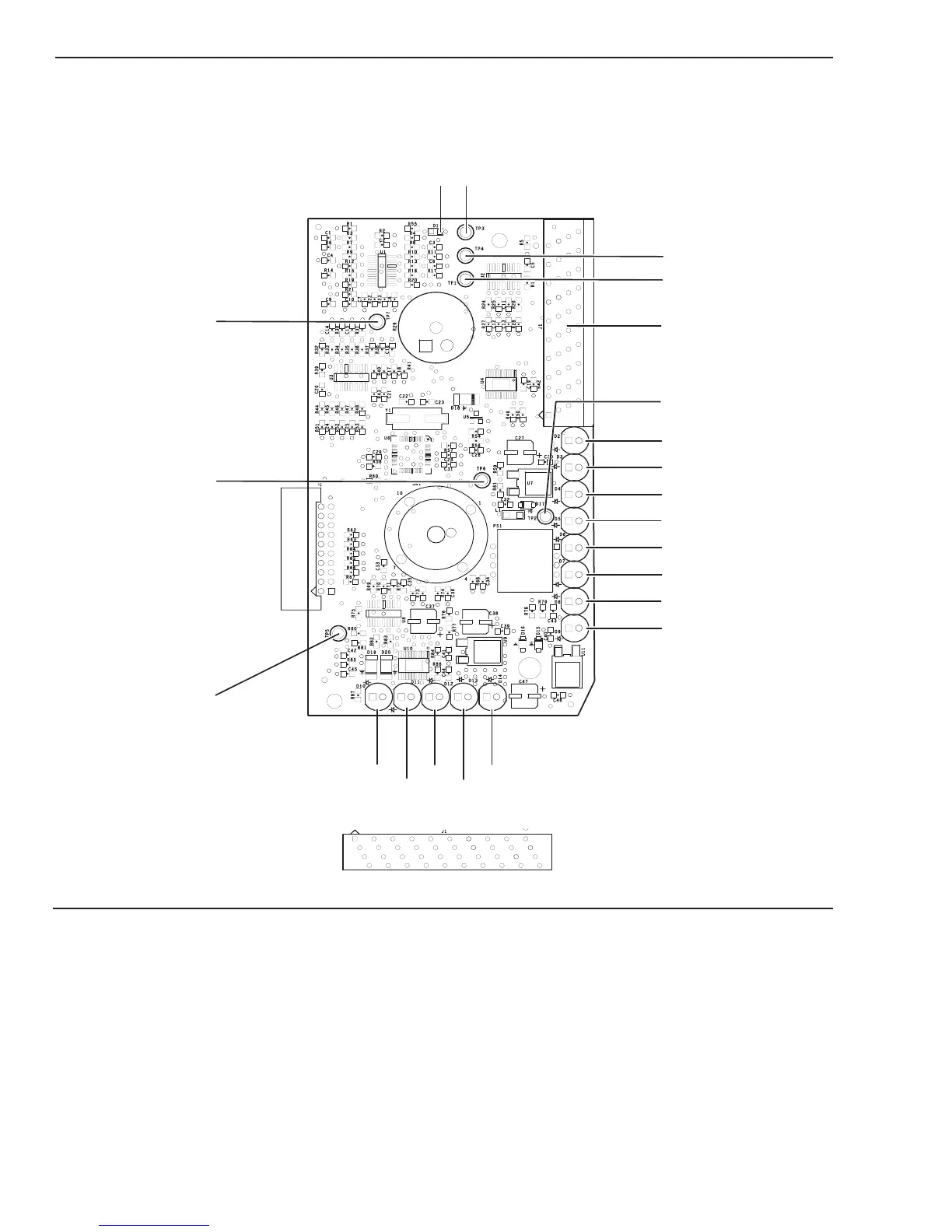
LOGIC PCB LAYOUT
PCB3
1
4
37
40
*J1 Pinout
TP2
Art # A-08179
LOGIC PCB SIGNALS (Same for MAIN PCB J2) Signal Source/Destination
J1-1 -VOUT (-) OUTPUT VOLTAGE M-L
J1-2 /TIP VOLTS Active high when tip is installed M-L
J1-3 TIP_SEN Approx. 100VDC while cutting with tip not in M-L
contact w/work piece, Active low when tip
contact work during cut (Drag Mode)
J1-4 /460V_IN Active low with 460vac primary input voltage L-M
J1-5 /230V_IN Active low with 230vac primary input voltage L-M
J1-6 CUR_SET Current demand signal. Variable 1-4VDC L-M
J1-7 /RAR Active low when in Rapid Auto Restart mode L-M
J1-8 /INRUSH Active low after inrush time expires L-M