Manual 0-2683 9 Introduction
2.3 Service Responsibilities
The Service Technician should be familiar with the equip-
ment and its capabilities and should be prepared to rec-
ommend arrangements of components which will provide
the most efficient layout, utilizing the equipment to its best
possible advantage.
Maintenance work should be accomplished in a timely
manner. If problems are encountered, or the equipment
does not function as specified, contact Technical Services
Department in West Lebanon for assistance.
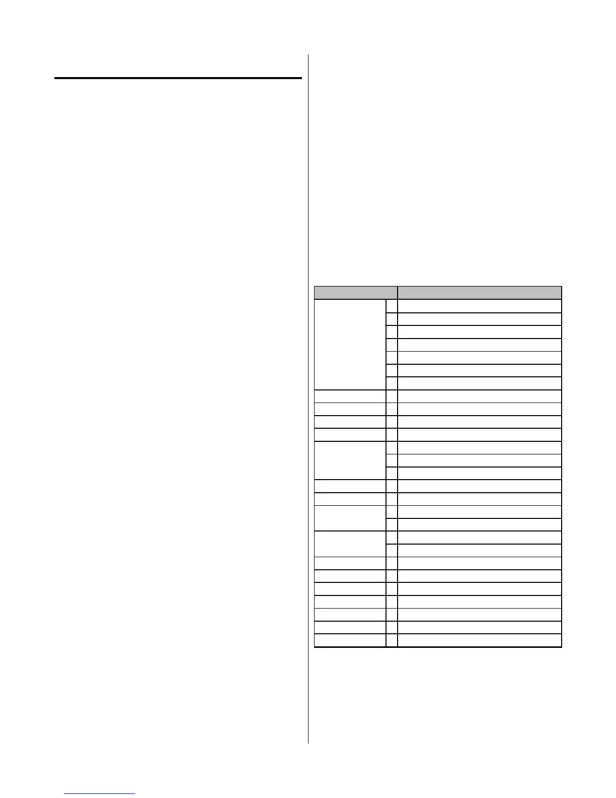
2.4 Technical Specifications
A. System Specifications
System Specifications
Input Power
100 VAC 50Hz, 110 VAC 60Hz, Single Phase
100/110 VAC, 50/60Hz, Single Phase
120VAC ±10%, 50Hz, Single Phase
120VAC ±10%, 60Hz, Single Phase
220VAC ±10%,50Hz, Single Phase
208/230VAC ±10%, 60Hz, Single Phase
Output Power See subsection 2.3B
Duty Cycle See subsection 2.3B
Maximum OCV 280 VDC
Pilot Circuitry Capacitive Discharge (CD), Constant DC
Weight with Leads 55 lbs (24.9 kg)
Power Supply L 16 in. (406 mm)
Dimensions W 9 in. (229 mm)
H 10 in. (254 mm)
Work Cable 15 ft. (4.6 m)
Input Power Cable 6.6 ft. (2 m) minimum
PCH-10 70°
PCH-10 180°
L See subsection 2.4
W See subsection 2.4
Cutting Rating 12 Amps Max. Straight Polarity
Cut Capacity Most metals up to 1/8 in. (3.2 mm) max.
Severance Most metals up to 3/16 in. (4.8 mm)
Pierce Rating 1/16 in. (1.6 mm)
Transfer Distance Approx. 1/8 in. (3.2 mm)
Gas Requirements Compressed Air (Built-in)
Leads Length 20 ft. (6.1 m)
Torch Style
Torch Dimensions
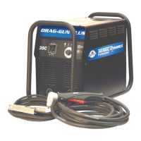
2.0 INTRODUCTION
2.1 Scope Of Manual
This manual provides service instructions for the Ther-
mal Dynamics® DRAG-GUN Plasma Cutter.
Information in this edition is particularly applicable to
the Troubleshooting and Repair of the equipment, and is
intended for use by properly trained Service Technicians
familiar with this equipment.
Read this manual and the DRAG-GUN Operating Manual,
0-2682, thoroughly. A complete understanding of the ca-
pabilities and functions of the equipment will assure ob-
taining the performance for which it was designed.
2.2 General Service Philosophy
Several key points are essential to properly support the
application and operation of this equipment.
A. Application
The equipment should satisfy the customer’s requirements
as supplied and as described in Section 3 of this manual.
Be sure to confirm that the equipment is capable of the
application desired.
B. Modifications
No physical or electrical modifications other than selec-
tion of standard options and accessories are to be made to
this equipment.
C. Customer/Operator Responsibilities
It is the customer/operator's responsibility to maintain
the equipment and peripheral accessories provided by
Thermal Dynamics in good operating order in accordance
with the procedures outlined in the Operating Manual,
and to protect the equipment from accidental or malicious
damage.
D. Repair Restrictions
The electronics consists of a Printed Circuit Board Assem-
bly which must be carefully handled, and must be replaced
as a unit. No replacement of printed circuit solder-mounted
components is allowed except as noted in this manual. If
PC Board is to be returned, the replaced Printed Circuit
Board Assembly must be properly packaged in protective
material and returned intact per normal procedures.
 Loading...