REPLACEMENT PROCEDURES 24 Manual 0-2683
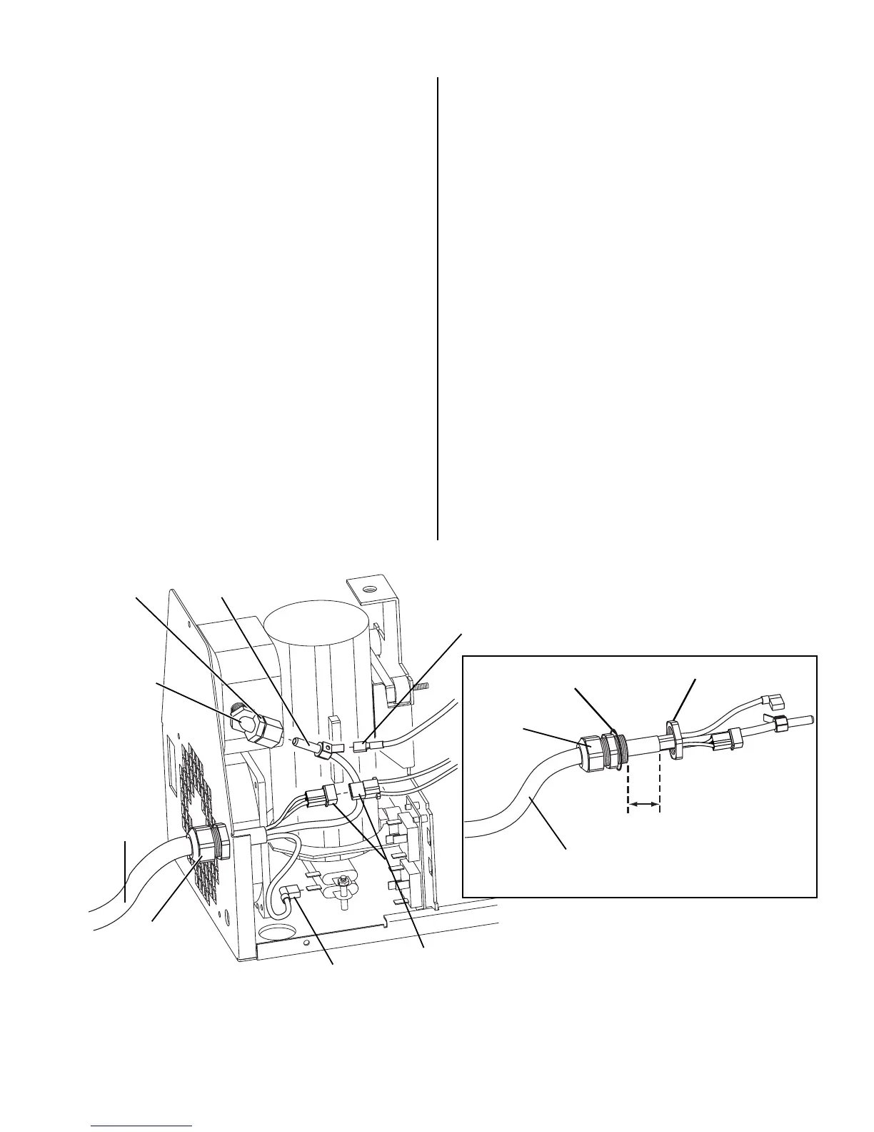
4.14 Torch & Leads Replacement
1. Remove cover/handle from unit per subsection 4.2.
2. Disconnect the following (refer to Figure 4-4):
• Faston Connector (to CD Coil) from the Brass
Torch Lead Fitting
• Brass Torch Lead Fitting from the 90 degree
White Nylon Fitting.
• 2-pin Connectors.
• Torch Lead Faston Connector (red) from bot-
tom Resistor.
3. Loosen the Strain Relief Nut from the Strain Relief
and remove Torch Lead Assembly from unit.
4. Install Strain Relief on replacement torch.
5. Insert Torch leads through front hole on unit.
6. Slide Strain Relief Nut over the end of the torch
lead.
7. Allow one inch clearance between the end of the
torch lead sheath and the hole in the front panel
then tighten the Strain Relief Nut. (This allows al-
low enough length in the torch lead to make all the
connections inside the unit.)
8. Reconnect all connections by reversing step 2.
9. Replace cover by reversing step 1.
Torch Leads Assembly
Strain Relief Nut
Strain Relief
1" Clearance
Strain
Relief
Torch Lead Faston Connector (Red)
(Connect to Bottom Resistor)
2-Pin Connectors
Torch
Lead
Faston Connector
to CD Coil
90˚ White
Nylon Fitting
Brass Torch
Lead Fitting
A-02009
Nylon Nut
Front Panel
Hole Location
Note: Do not remove strain relief from torch lead.
Figure 4-4 Torch & Leads Replacement
 Loading...