Manual 0-2683 25 REPLACEMENT PROCEDURES
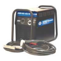
4.15 Work Cable Replacement
1. Remove cover/handle from unit per subsection 4.2.
2. Disconnect the Work Cable Faston from mounting
tab on bottom of Rectifier.
3. Loosen Strain Relief and remove Work Cable from
unit.
4. Install Strain Relief on replacement Work Cable 5
1/2 inches from Faston.
5. Install replacement Work Cable by reversing steps
1-3.
Work Cable
Strain Relief
(Install 5 1/2" from Faston)
A-02011
Work Cable Faston
(Connect to mounting
tab at bottom of Rectifier
)
Bridge
Rectifier
Figure 4-5 Work Cable Replacement
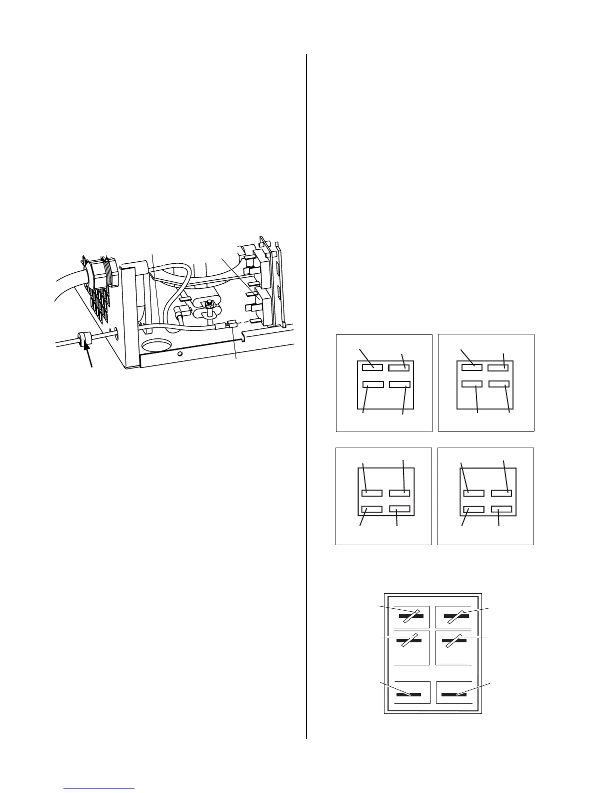
4.16 Primary Input Power Cable
Replacement
1. Remove cover/handle from unit per subsection 4.2.
2. Disconnect Input Power Cable wiring to the ON/
OFF Switch and Ground.
3. Loosen Input Power Cable Strain Relief and re-
move Input Cable from unit.
4. Install Strain Relief on replacement Input Power
Cable.
5. Install the Input Power Cable through rear panel.
6. Check the wire numbers on the Input Power Cable
and the prong numbers on the ON/OFF Switch.
Match that information to one of the configura-
tions in Figure 4-6 and connect the wires accord-
ingly.
A-02652
Black (Brown)
Wire
Black Wire
#5
Black Wire
#6
White (Blue)
Wire
11
12
24
25
A
Black (Brown)
Wire
Black Wire
#21
Black Wire
#22
White (Blue)
Wire
11
12
24
25
B
C
1
4
2
5
D
Black Wire
#5
1
4
2
5
Black Wire
#21
Black Wire
#6
Black Wire
#22
Black (Brown)
Wire
White (Blue)
Wire
White (Blue)
Wire
Black (Brown)
Wire
A-03649
White or
Blue Wire
Brown or
Black Wire
4B
1A
5B
2A
6B
3A
Not Used
Wire No. 5
or 21
Wire No. 6
or 22
E
Not Used
Figure 4-6 Input Power Cable Connections

 Loading...