Manual 0-2683 21 REPLACEMENT PROCEDURES
B. To Install Replacement PC Board:
1. Install replacement key slotted PC Board by plac-
ing PC Board over standoffs and sliding Board
down into position.
2. Push a white fastener plastic push on into each
keyhole (just above standoffs) to secure the PC
Board into position.
3. Reverse steps 1-4, keeping in mind the following:
a. Make sure J2 is not offset by one or more pins.
b. Install new tie wraps on wires connected to the
PC Board, as necessary.
4.8 Power Relay Replacement
NOTES
The Control PC Board must be moved out of the
way before the Power Relay can be replaced. (It may
be easier to move the Control PC Board if the Ca-
pacitor is removed first.)
Refer to subsection 4.1, General Information, for
information about wire harnesses.
WARNING
Disconnect primary power to the system before dis-
assembling the torch, leads, or power supply.
1. Remove cover/handle from unit per subsection 4.2.
2. Remove Capacitor (optional step) per instructions
in 4.6.
3. Remove PCB from standoffs per subsection 4.7.B.
4. Slide PC Board away from Relay.
5. Note all wiring connections and locations to the
Relay.
6. Remove wirings connected to Relay.
7. Slide Relay out from bracket, towards the center of
the unit.
8. Install replacement Relay, by reversing the above
steps, keeping in mind the following:
a. Position wire connector L4 so that it runs along
side the Transformer, NOT across the top of the
Transformer.
4.9 ON/OFF Power Switch
Replacement
NOTE
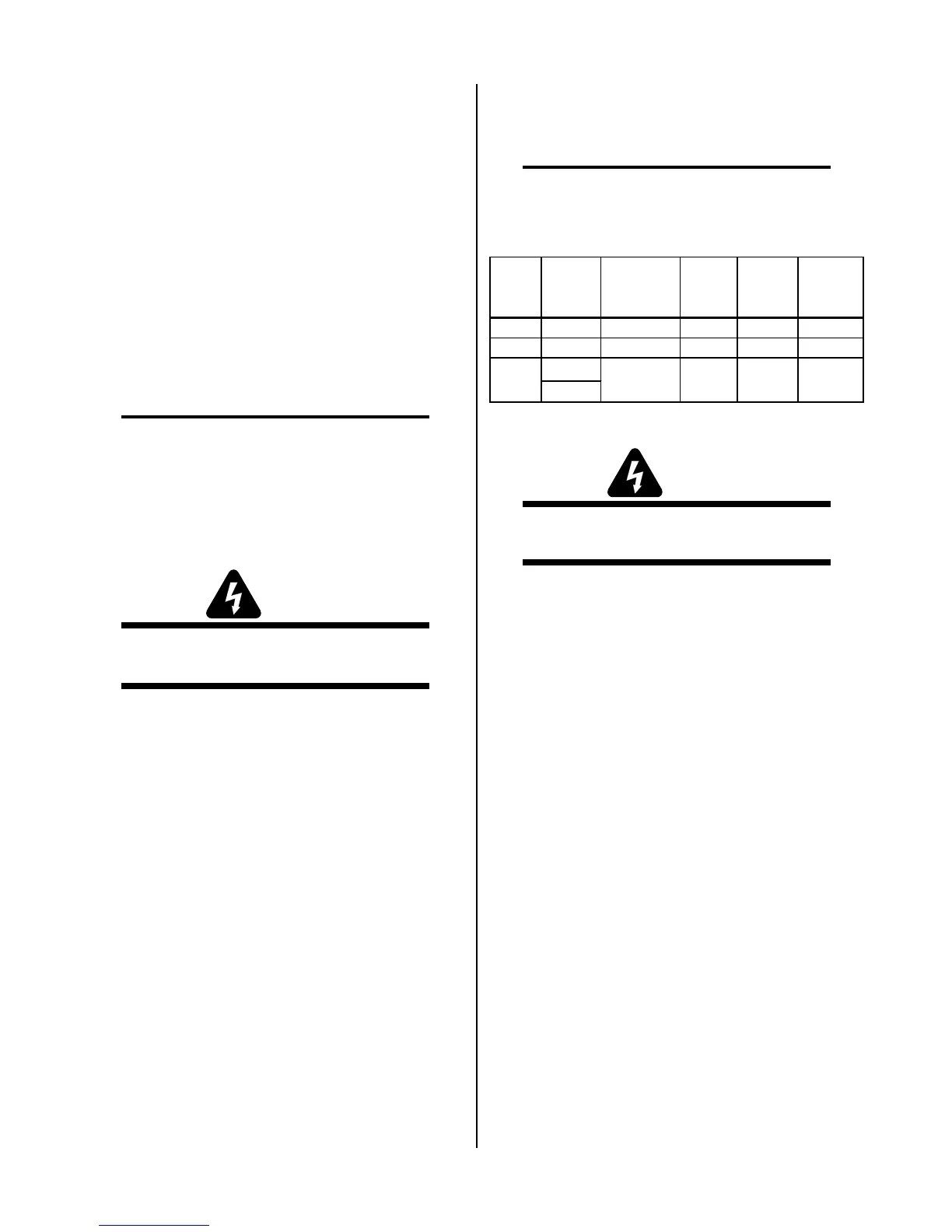
When ordering a replacement ON/OFF Switch,
order the same as found in your unit. ON/OFF
Switches are as follows:
Model
Switch
Type
Size
Neon
Color
Voltage
Catalog
Number
A
5 prong 1" x 2" Red 115 9-0015
B
4 prong 1" x 1-1/4" Red 115 9-0021
4 prong
6 prong
C
Amber
or Red
220 9-00291" x 1-1/4"
WARNING
Disconnect primary power to the system before dis-
assembling the torch, leads, or power supply.
A. Models A & B:
1. Remove cover/handle from unit per subsection 4.2.
2. Note all wiring connections and locations to the
On/Off Switch.
3. Disconnect wires to ON/OFF Switch.
4. Push plastic clips down on top side of Switch and
slide Switch out by pulling it through front panel.
5. Install replacement ON/OFF Switch, by reversing
the above steps, keeping in mind the following:
a. Position wire connector L4 so that it runs along
side the Transformer, NOT across the top of the
Transformer.

 Loading...