Manual 0-2683 19 REPLACEMENT PROCEDURES
4.4 Torch Switch Only
Replacement
NOTE
This procedure requires the following tools (or
equivalent): screwdriver, soldering iron, Flux.
WARNING
Disconnect primary power to the system before dis-
assembling the torch, leads, or power supply.
1. Remove consumable parts from front end of torch.
2. Remove the six screws from the torch handle as-
sembly and remove torch and leads assembly.
3. Using soldering iron, carefully remove solder
where orange wire connects to switch terminal.
NOTE
Be careful not to overheat the torch switch while
removing soldering from terminals.
4. Apply Flux to orange wire and to switch post. In-
sert orange wire in switch post hole and solder,
keeping solder at a minimum required for good
joint.
5. Repeat steps 3 and 4, this time for the white wire.
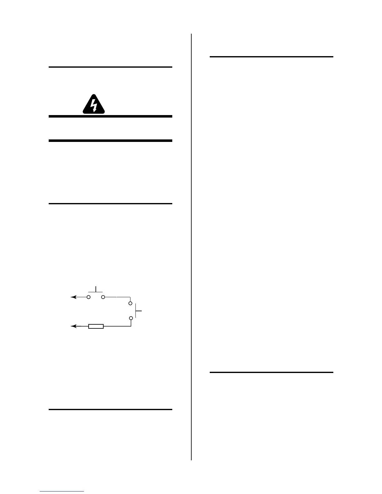
Torch Switch
PIP Pin
PIP Pin
Shield Cup
To Control
Cable Wiring
Butt Splice
A-00784
Figure 4-3 Torch Switch Schematic
6. Place the torch head in the torch handle bottom.
Carefully return the torch switch and button w/
springs to their proper position. Replace cover on
the handle assembly, and screw together with six
screws.
NOTE
Make sure torch switch wires are seated in their
guides so that the wires are not pinched when the
handle is secured.
7. Install consumables parts in front end of torch.
4.5 Air Compressor Replacement
NOTES
Refer to subsection 4.1, General Information, for
information about wire harnesses.
Refer to Appendix II for parts location and orienta-
tion.
1. Remove cover/handle from unit per subsection 4.2.
2. Locate the nylon nut on the 90° nylon fitting on
side of Air Compressor. Loose the nylon nut and
slide the brass torch lead fitting/faston connector
out.
3. Complete one of the following, as it pertains to
your unit:
• Rev C units or earlier - Disconnect black wire
from Compressor to faston splice & wire #21.
Disconnect red wire from Compressor to up-
per diode piggy back terminal.
• Rev D units or later - Disconnect black wire
from Compressor to faston splice & wire #29.
Disconnect red wire from Compressor to up-
per diode piggy back terminal.
4. Slide Compressor out of bracket.
5. Note position and angle of 90° nylon nut connected
to the Air Compressor Remove fitting.
6. Clean old teflon thread sealant from nylon fitting,
apply new thread sealant and install nylon fitting
on replacement Air Compressor. Make sure fitting
is in proper position.
7. Remove “feet” from Compressor and install on re-
placement Compressor.
8. Insert replacement Air Compressor into bracket,
insuring “feet” have dropped into slots in bracket.
9. Apply a small amount of O-Ring lubricant to brass
torch fitting and insert into 90° nylon fitting.
Tighten nylon nut.
NOTE
Be careful not to remove the nylon nut completely
as there are small parts inside that could fall out.
10. Connect the following as it pertains to your unit:
• Connect black wire from Compressor to faston
splice & wire #21. Connect red wire from Com-
pressor to upper diode piggyback terminal.
• Connect black wire from Compressor to faston
splice & wire #29. Connect red wire from Com-
pressor to upper diode piggyback terminal.

 Loading...