REPLACEMENT PROCEDURES 18 Manual 0-2683
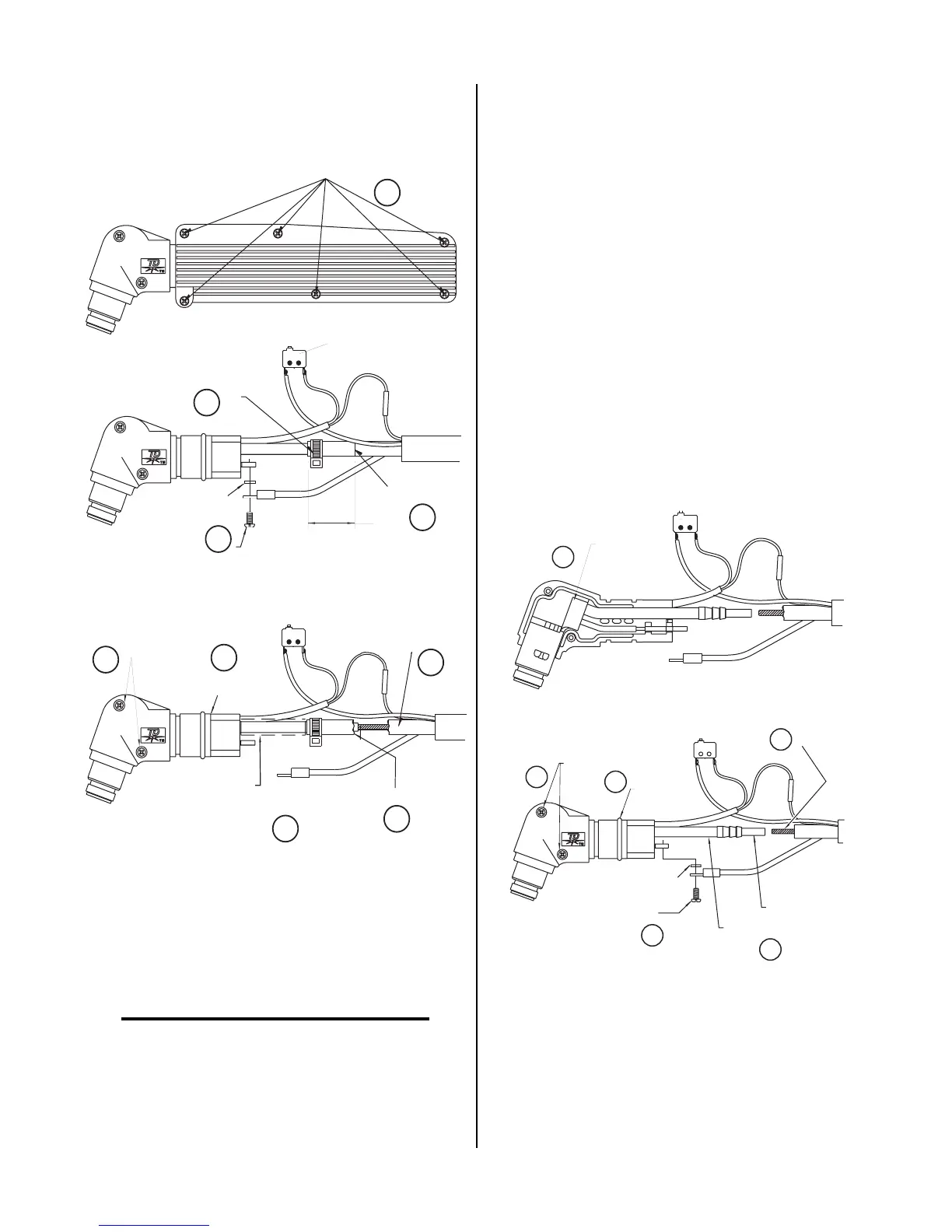
1.000
O-Ring
Remove Screws
Orange Torch
Sleeving
(Optional)
Cut Cable Here
Place Vise
Grips Here
Remove Pilot
Lead Screw
Cut Black
Hose
Cut Tie Wrap
Remove Six Screws
Switch
A
B
C
D
E
F
G
H
I
A-02295
Washer
Figure 4-1 Removing Torch HeadAssembly
To Install Replacement Torch Head Assembly:
NOTE
Refer to Figure 4-2 for parts identification.
1. Place replacement torch head in torch head split
holder halves and secure with 2 screws removed
in step 9 above (K). Do not disturb PIP connec-
tions.
2. Install O-ring removed in step 8 above (L).
3. Optional: Install orange sleeving on replacement
torch head gas input.
4. Place torch head in correct orientation, then insert
lead cable into torch butt slice and crimp (M).
5. Remove vise grips.
6. Lubricate torch head glands lightly with silicone
and push hose back onto barbs up to the point
where the teflon tubing and brass fitting meet (N).
7. Install tie wrap onto hose in correct position (C),
removing any excess.
8. Connect pilot lead to pilot lead terminal by plac-
ing washer between terminal and connector and
installing screw (O).
9. Push pilot lead under cable jacket until there is no
excess.
Install Pilot
Lead Screw
Butt Splice
Insert Cable Into
Butt Splice & Crimp
Install
O-Ring
Install Screws
New Torch Head
J
K
M
N
Teflon Tubing
A-02296
L
O
Washer
4-2 Installing Torch Head Assembly
 Loading...