Manual No. 0-4819 2-1 SPECIFICATIONS
SECTION 2: SPECIFICATIONS
General Description Of The System
A typical Ultra-Cut
®
300 system configuration includes:
• One Power Supply
• Remote Arc Starter
• Gas Control Module
• Torch Valve Assembly
• Precision Plasma Cutting Torch
• Set Of Connecting Leads
• Torch Spare Parts Kit
The components are connected at installation.
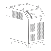
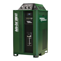
Plasma Power Supply
The power supply provides the necessary current for cutting operations. The power supply also monitors system
performance, and cools and circulates the liquid coolant for the torch and leads.
Remote Arc Starter
This unit produces a temporary HF pulse to start the pilot arc. The pilot arc creates a path for the main arc to
transfer to the work. When the main arc is established, the pilot arc shuts off.
Gas Control Module
This module allows remote setting of gas selection, pressures, and flows together with setting of cutting current.
Precision Plasma Cutting Torch
The torch delivers the controlled current to the work through the main arc, causing the metal to be cut.

 Loading...
