Manual No. 0-4819 3-15 INSTALLATION
D. Routing Of Torch Leads
1. To minimize RF interference, position torch leads as far as possible from any CNC components, drive motors,
control cables, or primary power lines. If cables have to pass over torch leads, do so at an angle. Do not run
the plasma control or other control cables in parallel with the torch leads in power tracts.
2. Keep torch leads clean. Dirt and metal particles bleed off energy, which causes difficult starting and increased
chance of RF interference.
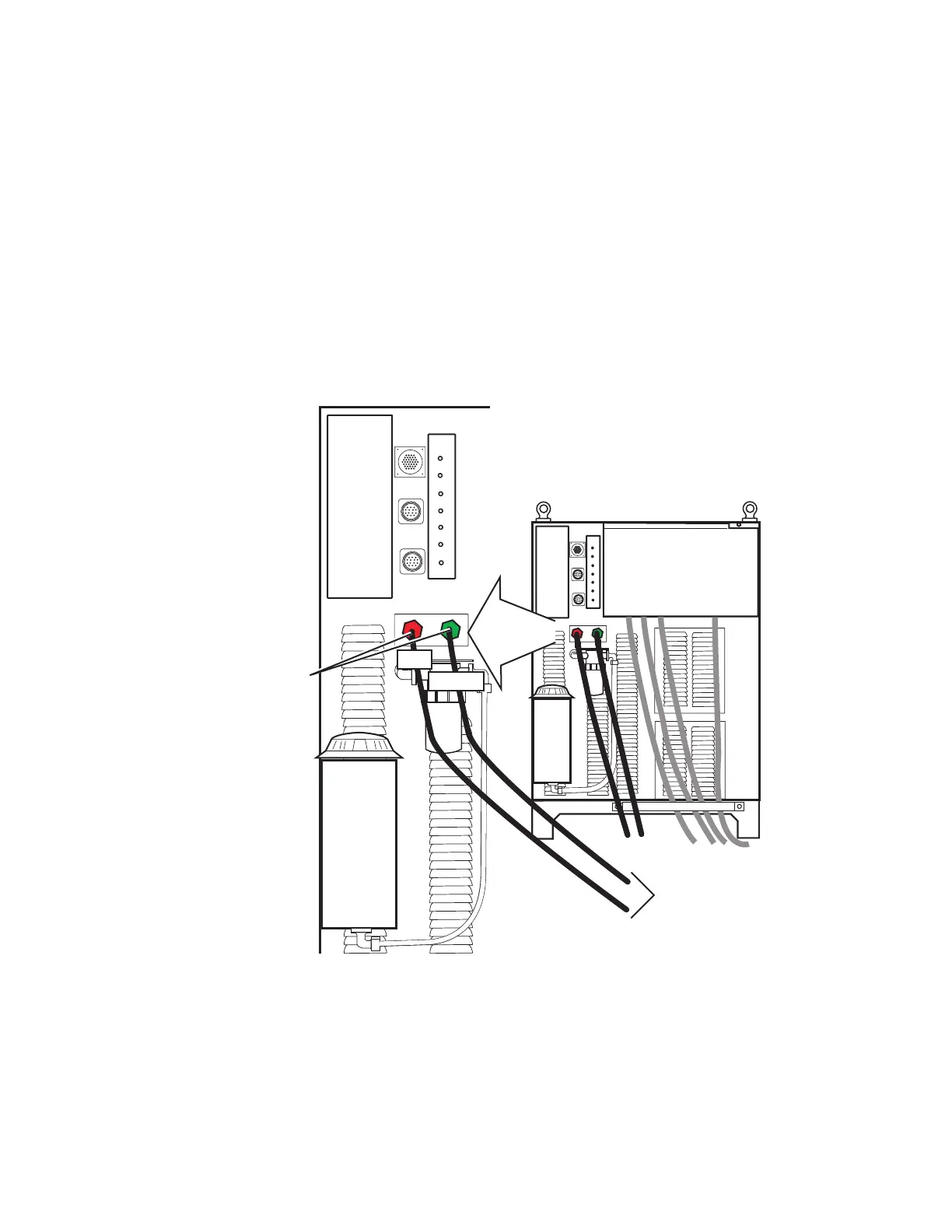
K. Connect Coolant Leads
1. Connect the color-coded coolant hoses to the coolant connections on the power supply rear panel. The
supply line (out) is flagged green, the return line (in) is flagged red.
Coolant Connections
RETURN
SUPPLY
RETURN
SUPPLY
Art # A-04800
To Remote Arc Starter
COOLANT
RED
GREEN
 Loading...


