Manual No. 0-4819 6-3 Power Supply Parts List
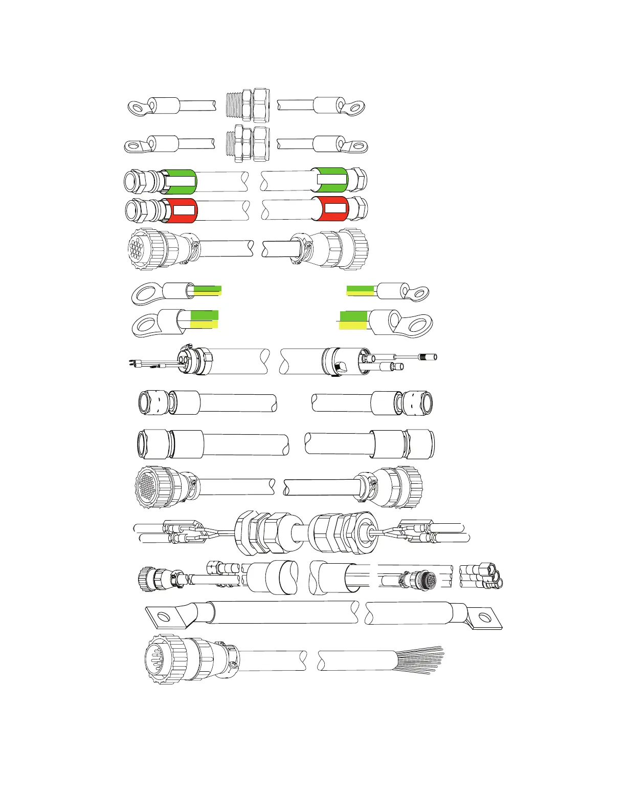
Leads and Cables
Green / Yellow # 4 AWG
Green / Yellow 1/0 (50 mm )
A
Green
Red
Art # A-07473
#8 AWG Cable
#1 AWG Cable
B
C
D
E
F
F1
K
L
H, Q,
R, S,T
Work Cable
CNC Cable (14 Wire)
37
14
Coolant Supply Lead,
Power Supply to Arc Starter
1/0 Cable (1/0 (50 mm )
Pilot Return, Power Supply
to Arc Starter
Negative Lead, Power Supply
to Arc Starter
Control Cable, Power Supply
to Arc Starter
Ground Cable
Ground Cable,
Remote Arc Starter
To Earth Ground
O
P
Fiber Optic Cable,
Power Supply to
Gas Control Module
Control Cable,
Power Supply to
Gas Control Module
Green
Red
Coolant Return Lead,
Power Supply to Arc Starter
2
2
14
G
Shielded Torch Lead
Assembly, Remote
Arc Starter to Torch
Plasma Gas Lead,
Torch Valve to Torch
Shield Gas Lead,
Torch Valve to Torch
I
J
 Loading...


