Manual No. 0-4819 4-4 OPERATION
Gas Control Module: Controls & Indicators
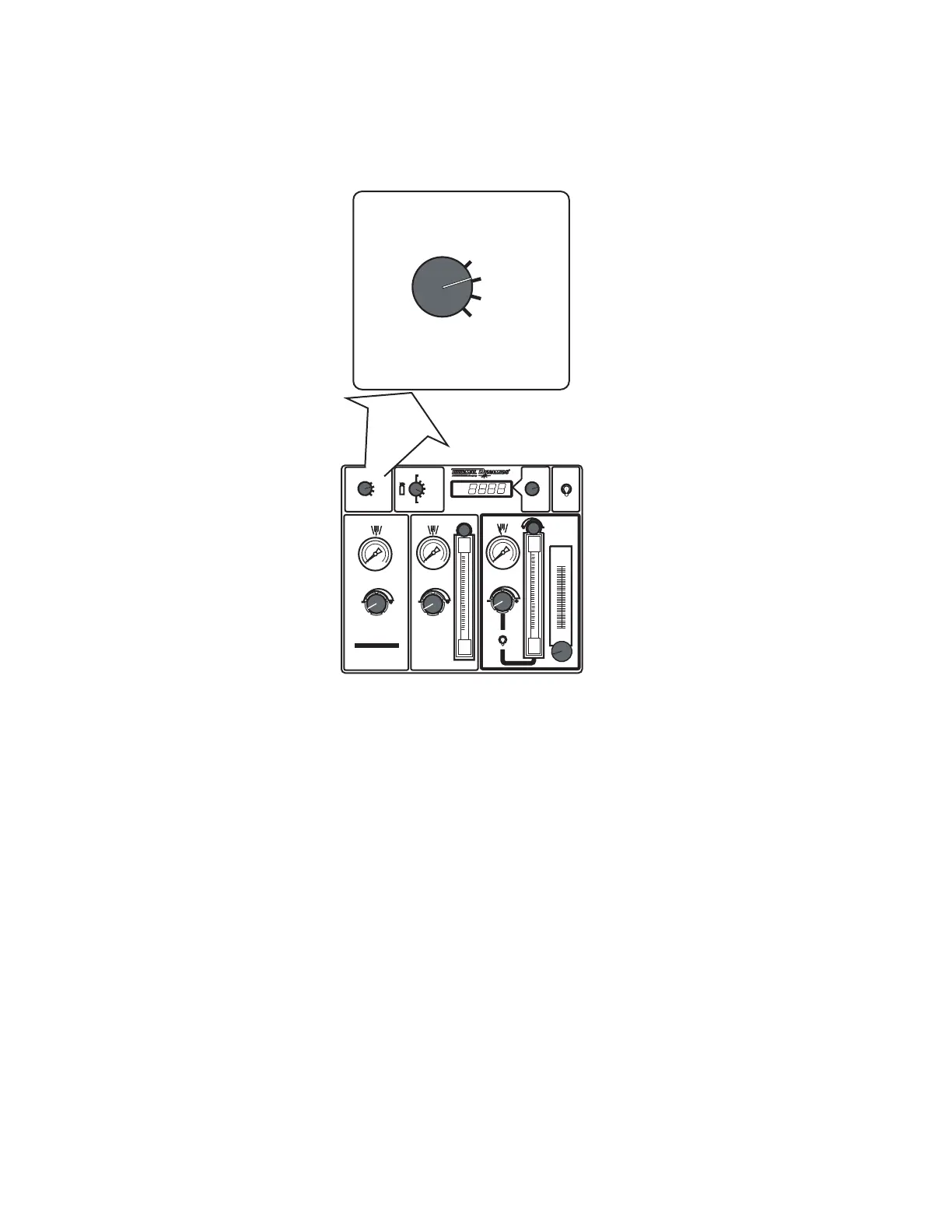
1. MODE Selection Switch
MODE
RUN
SET PREFLOW
SET PLASMA
& SHIELD
TEST
PREFLOW
H
2
O
MIST
PLASMA
SHIELD
PRESSURE
PLASMA
POWER SUPPLY
GAS
FLOW
AMPERAGE
SET-UP
High Precision
Plasma Cutting System
ENABLE
DISABLE
GAS
MODE
RUN
SET PREFLOW
SET PLASMA
& SHIELD
TEST
O2 - AIR
O2 - O2
H35 -N
2
F5 - N2
AIR - AIR
N
2 - H2O
N
2 - N2
Art # A-04765
9
9
GCM
2010
• Normally in the RUN position during torch operation.
• In the SET PREFLOW position, Air or N2 travels to the torch. The Preflow valve remains open for 2 minutes
to allow the operator to adjust flow pressure.
• In the SET PLASMA & SHIELD position, gases travel to the torch. The Preflow valve at the torch remains open
for 2 minutes to allow the operator to adjust flow pressures and rates.
• In the TEST position, gases fill the torch leads. The display shows the pressure of the plasma gas while
flowing. After 1 minute the Module shuts off the valves at the torch.
 Loading...


