Manual No. 0-4819 3-11 INSTALLATION
H. Check / Adjust Input Voltage Configuration
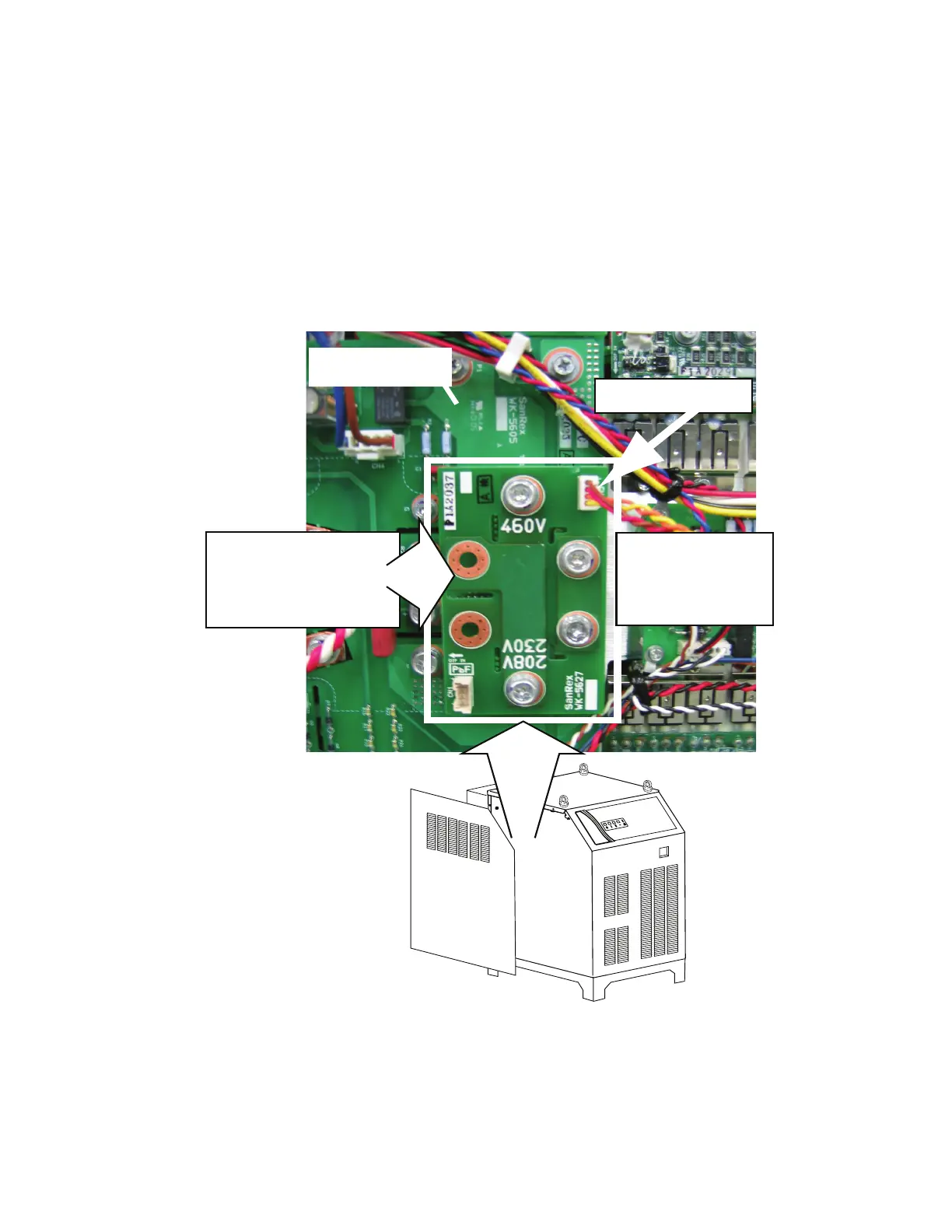
1. The power supply includes a voltage configuration board which must be positioned to match the primary
input voltage. Remove the power supply left side panel and locate the voltage configuration board. The input
voltage configuration is shown at the top of the board.
2. If necessary, disconnect the jumper at the top right corner of the board, remove the board and re-install it with
the correct input voltage shown at the top of the board.
3. Re-connect the jumper. Re-install the power supply side panel.
Art # A-04856
1. Disconnect jumper
2. Remove bolts.
3. Invert board.
4. Re-install board.
5. Connect jumper.
208/230V / 460V
Input Voltage Board
(Shown in 460V Position)
Inverter Module
 Loading...


