Installation
Connecting External Devices
2-6 Model 49i Primary Standard Instruction Manual Thermo Fisher Scientific
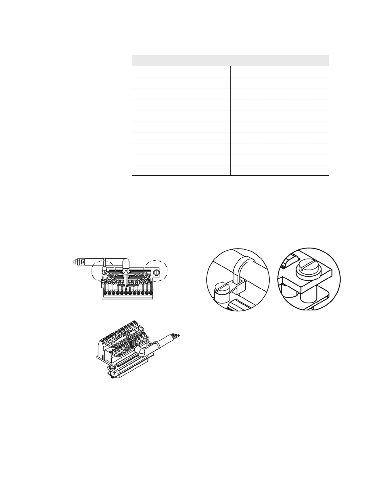
D/O Terminal Board Figure 2-5 shows the recommended method for attaching the cable to the
terminal board using the included tie-down and spacer. Table 2-2 identifies
the connector pins and associated signals.
Figure 2-5. D/O Terminal Board Views
3 Analog2 15 Power_Fail_NO
4 Analog ground 16 TTL_Input1
5 Analog3 17 TTL_Input2
6 Analog ground 18 TTL_Input3
7 Analog4 19 TTL_Input4
8 Analog ground 20 Digital ground
9 Analog5 21 TTL_Input5
10 Analog ground 22 TTL_Input6
11 Analog6 23 TTL_Input7
12 Analog ground 24 Digital ground
Table 2-1. I/O Terminal Board Pin Descriptions, continued
Pin Signal Description Pin Signal Description
Component Side Viewed from Top of Board
Assembled Connector
See Detail “A”
Detail “A”
See Detail “B”
Detail “B”



 To Next Page