Do you have a question about the Thermo 42i and is the answer not in the manual?
Explains the chemiluminescence detection principle of the analyzer.
Lists the analyzer's performance characteristics and technical data.
Procedures for safely removing the instrument from its packaging and checking for damage.
Step-by-step guide for connecting sample, air, exhaust, and power.
Instructions for powering on the instrument and initial warm-up procedures.
Describes the functions and information shown on the LCD graphics display.
Details the front panel pushbuttons and their intended actions.
Provides a high-level view of the menu-driven software structure.
Allows selection of gas units and defining concentration ranges.
Details how to adjust calibration factors for accurate readings.
Manages instrument settings like ozonator, PMT, and communication.
Provides access to system status, voltages, and temperatures.
Lists monitored items and their alarm status.
Accesses advanced functions for adjustments and diagnostics.
Lists necessary items for performing instrument calibration.
Outlines essential steps before starting the calibration process.
Procedure for setting instrument gain for accurate measurements.
Describes how to verify and maintain instrument calibration.
Important safety guidelines to prevent injury or equipment damage.
Procedure for checking and replacing instrument capillaries.
Maintenance steps for the PMT cooler fins.
Instructions for overhauling the instrument's pump.
Essential safety guidelines for troubleshooting procedures.
Provides common malfunctions and their solutions.
Contact information for technical support.
Critical safety warnings for service personnel.
Lists part numbers for instrument components.
Steps to access internal components.
Procedure for replacing the HV power supply.
Steps for cleaning or removing the reaction chamber.
Procedure for replacing the converter assembly.
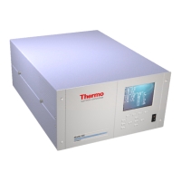
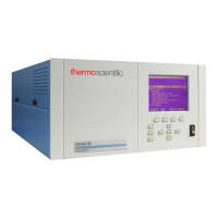
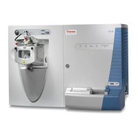
Describes the physical components of the analyzer.
Overview of the analyzer's software structure and tasks.
Details the system boards and their functions.
Describes input/output interfaces and connectors.
Description of an optional valve system.
Details different ways to install the analyzer.
Provides terms and conditions of the product warranty.
Lists and describes available C-Link commands.
Details commands for retrieving measurement data.
Describes commands for accessing alarm status.
Details commands related to instrument calibration.
Commands for configuring measurement parameters.
Commands for managing hardware settings.
Commands for network and serial communication setup.
Commands for managing digital and analog I/O.
Explains data format specifications.
| Measurement Principle | Chemiluminescence |
|---|---|
| Detection Limit | 0.4 ppb |
| Resolution | 0.1 ppb |
| Power Requirements | 100-240 V AC, 50/60 Hz |
| Measurement Range | 0 - 20 ppm (other ranges available) |
| Linearity | ±1% of full scale |
| Operating Humidity Range | 0 - 95% RH, non-condensing |
| Outputs | Analog |
| Display | Backlit LCD |
