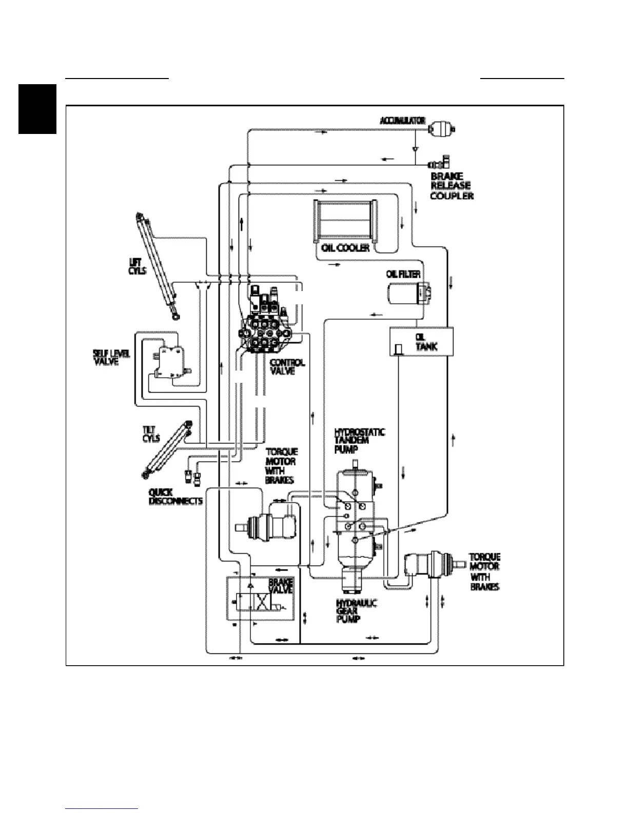
HYDRAULIC LAYOUT 1.1
A Auxiliary Circuit
B Tilt Circuit
C Lift Circuit
NOTE: Foot pedal control operated machine illustrated.
Items (A3 / B3) are reversed for hand control operated
machines.
Hydraulic fluid comes out the port closest to the spool
end of the valve when the spool is pushed in.
Hydraulic fluid received at the fixed end of the cylinder
pushes it out. When the hydraulic cylinder receives fluid
at the ram (rod) end, it retracts.
1-2
B B
AA
C C
C4165