4-15
Control Lever Replacement
1 Raise the boom arms, engage the boom supports and
shut off the engine.
2 Remove the seat and hydrostatic shield.
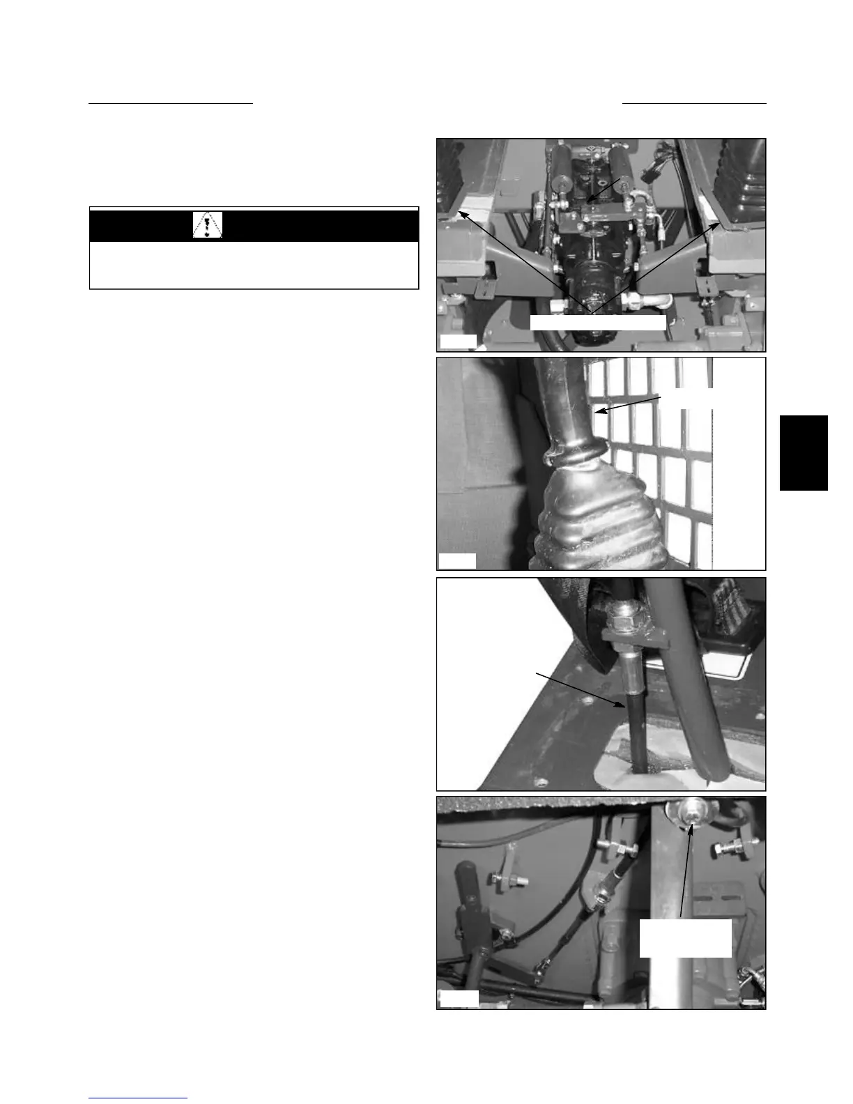
3 Remove control lever plates and boots. Disconnect
throttle if necessary. (fig. C3876, C3832)
4 Remove cotter pins from the lever base ass’y and
cable and remove the clevis pin. (fig. C3848)
5 Loosen the cable nuts and remove cable from mount
on control lever.
6 Remove bolts from control rod.
7 Remove mounting bolts for control lever. (fig.
C3847)
8 Remove control lever saving the plastic sleeve.
Replace if necessary.
9 Replace all parts in reverse order. Cycle the control
lever after installation to check for binding and travel
clearance. Check control angles, wheel speed and track-
ing to ensure optimum performance.
NOTE: If the loader is equiped with optional electronic
accessories operated by control handle mounted switches,
the control handle switch wiring will need to be discon-
nected and transferred to the new steering lever.
If the control lever functions are sloppy due to excessive
wearing of the swivel bushing, the swivel assembly may
need replaced.
C3832
C3848
C3876
Control Lever Cover
C3847
HAND CONTROLS 4.3
WARNING
Never work under the boom arms without the boom
supports engaged.
Control Handle
Control Cable
Remove The
Mounting Bolt