
A
ahenryAug 13, 2025
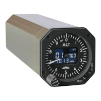
What to do if the digital display is blank on my Thommen AD20?
- JjohnsonjonathanAug 13, 2025
If the digital display on your Thommen Measuring Instrument is blank, the issue might stem from a power supply failure, so ensure the power supply is working correctly. Alternatively, it could be due to an input signal failure; in this case, verify the input signal. A third possibility is an electronic module failure, which would require repairing the electronic module.