REVUE THOMMEN AG
CH-4437 Waldenburg
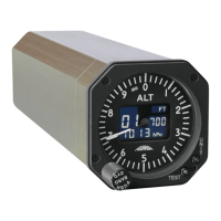
AD20 Standby Altimeter
Page 41 of 72
07-Sep-2009 Document No: AD-INSOP-800 Revision: 1.6
4 Section IV
4.1 Installation
4.1.1 General
Installation data in this section consists of pre-installation checks, Electrical Interface, system
interconnect diagrams and digital interface data to assure satisfactory performance of REVUE
THOMMEN AD20 Standby Altimeter Instrument.
NOTE: Refer to Section I part D for Mechanical Installation details.
4.1.2 Unpacking and Inspecting
Unpack the equipment carefully and make a visual inspection of the instrument for possible shipping
damage. If a claim for damage is to be made, save the original packing carton and materials to
substantiate the claim.
4.1.3 Pre and Post Installation Check
Before installing the instrument in the aircraft, check for the applicable configuration ID and correct
MOD status to ensure that the equipment meets performance specifications. The REVUE
THOMMEN AD20 Standby Altimeter does not require any in-aircraft adjustment. All adjustments
procedures are accomplished by the manufacture.
4.1.4 Electrical Interface
4.1.4.1 Overview of electrical interface
The following are the electrical interfaces for REVUE THOMMEN AD20 Standby Altimeter:
• Primary Power Supply
• Lighting Power Supply
• Digital Communication Interfaces (optional ARINC 429 data bus, RS232 Maintenance IF)
• Discrete I/O’s
4.1.4.2 Power Control (DC Primary)
The REVUE THOMMEN AD20 Standby Altimeter is designed for 28 VDC power supply in
accordance with RTCA/DO-160D Section 16.0 under Category Z.
4.1.4.3 Power Consumption
The following table shows values of power consumed by REVUE THOMMEN AD20 Standby
Altimeter instruments with the full operating functionality. The instruments e.g. without ARINC429
module or without sensors have less power consumption.
The power consumption by the REVUE THOMMEN AD20 Standby Altimeter at different stages of
operation are shown below in the table: