REVUE THOMMEN AG
CH-4437 Waldenburg
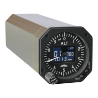
AD20 Standby Altimeter
Page 47 of 72
07-Sep-2009 Document No: AD-INSOP-800 Revision: 1.6
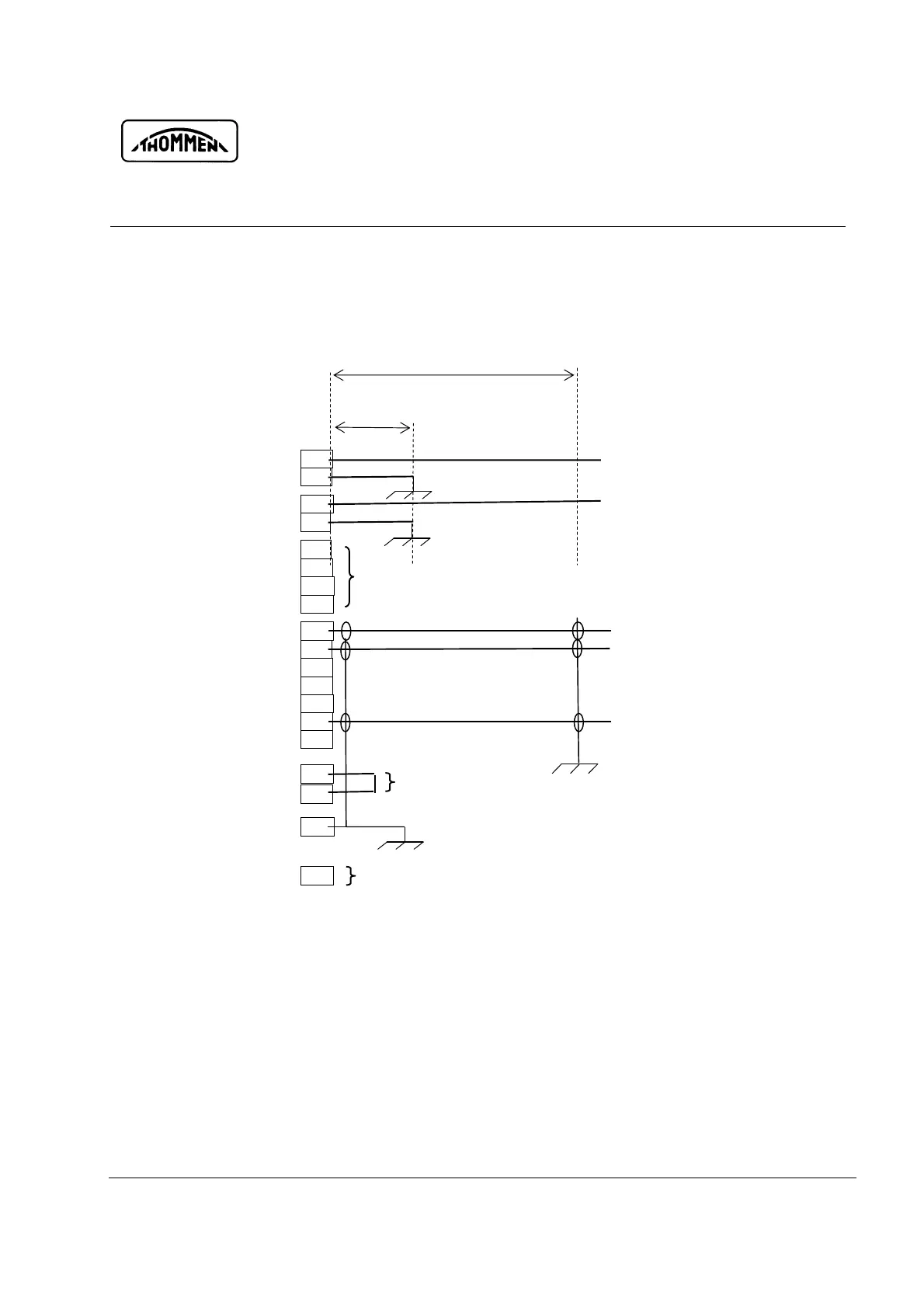
4.1.5.3 Wiring Diagram (unshielded power wires, RF Susc. Cat. [WW])
Fig. 4-3 Wiring Diagram (unshielded power wires)
E
F
U
J
L
K
M
N
T
P
B
D
V
A
R
S
Primary Power Supply
Primary Power Return
Lighting Supply
Lighting Return
ARINC429, TxD 1A
ARINC429, TxD 1B
ARINC429, TxD 2A
ARINC429, TxD 2B
Discrete Input 1
Discrete Input 2
Discrete Input 3
Discrete Input 4
WFVOUT, Discrete Output 0
Discrete Output 1
RS232, RxD
All wire gages 20 AWG ≈ 0.5 mm2
Wire length 3.3 m, unshielded
C
TEST, Discrete Input 0
Pin C (Test)
Pin V (Warning Flag Valid)
G
Chassis GND
RS232, TxD
Wire length 3.3 m, shielded
Pins P, B, D, A not connected
Pin T (Metric Selection)
H
Not connected
Pin G to shield and GND-Strap from connector shell to GND-Plane
Wire length 1 m
Provision, not connected
Wire loop length 7.5 cm
Wire length 1 m,
unshielded