REVUE THOMMEN AG
CH-4437 Waldenburg
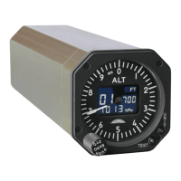
AD20 Standby Altimeter
Page 23 of 72
07-Sep-2009 Document No: AD-INSOP-800 Revision: 1.6
2.3 Operations
This part of the manual is to familiarize the reader with the REVUE THOMMEN AD20 Standby
Altimeter instrument and to give a brief operational description.
Caution:
The REVUE THOMMEN AD20 Standby Altimeter has been designed to exhibit a very high degree of
functional integrity. However it is possible that erroneous operation could occur without fault
indication. It is the responsibility of the operator to detect such an occurrence by means of cross
check with redundant or correlated information available in the cockpit.
2.3.1 Theory of Operation
2.3.1.1 Power Supply
The REVUE THOMMEN AD20 Standby Altimeter is designed to operate from a 28 VDC power
supply in accordance with RTCA/DO-160D Section 16.0 Category Z. The instrument requires
maximum of 1.4 W power consumption for normal operation (without display lighting power
consumption). The power consumption of 1.7 Watts maximum is with lighting.
2.3.1.2 Micro Controller
The Micro Controller is a flash type micro controller. The CPU has an internal 32-bit architecture
which is provided with sixteen 16-bit general registers and a concise, optimized instruction is
designed for high-speed operation. The CPU can also address a 16-Mbyte linear address space.
The operating voltage and the port power voltage of the Micro controller is +3.3 VDC. A crystal
oscillator of 4 MHz is connected to the micro controller and an internal clock generator produces the
system clock of 16 MHz.
2.3.1.3 ARINC 429 Interface (optional)
The ARINC 429 module in REVUE THOMMEN AD20 Standby Altimeter supports the ARINC-I/O
interface and the bus interface to the CPU.
The ARINC 429 offers the following main features:
• Two transmitter ports
• ARINC Low-Rate & High-Rate support with appropriate slew-rate control
• Multiple local loop-back facilities for improved BIT
• Lightning Induced Transients Suppression compliant with RTCA/DO-160D
• Hardening against aircraft wiring errors on ARINC inputs
Digital Data Standards are acc. to ARINC 429 Mark 33 DITS and ARINC 706-4 Mark 5 SADS /
equipment ID 006.