REVUE THOMMEN AG
CH-4437 Waldenburg
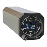
AD20 Standby Altimeter
Page 3 of 72
07-Sep-2009 Document No: AD-INSOP-800 Revision: 1.6
TABLE OF CONTENTS
1 SECTION I..................................................................................................................................... 10
1.1 Introduction..............................................................................................................................10
1.1.1 Purpose of the manual ...................................................................................................... 10
1.1.2 Equipment Specification.................................................................................................... 10
1.1.2.1 Applicable Documents .................................................................................................. 10
1.1.2.2 Identification ..................................................................................................................13
1.1.2.2.1 Type Identification Drawing .................................................................................... 13
1.1.2.2.2 Identification/Name Plate ........................................................................................ 14
1.1.2.3 Installation Kit ................................................................................................................15
1.1.3 Technical Specification ..................................................................................................... 15
1.1.4 Equipment Dimensions ..................................................................................................... 16
1.1.5 Pneumatic Pressure Port .................................................................................................. 17
1.1.6 Interface Block diagram .................................................................................................... 18
2 SECTION II.................................................................................................................................... 19
2.1 General Information................................................................................................................19
2.2 Description............................................................................................................................... 19
2.2.1 Instrument Description ...................................................................................................... 19
2.2.2 Functional Description....................................................................................................... 20
2.2.2.1 Display ........................................................................................................................... 21
2.2.2.1.1 Digital Altitude Display ............................................................................................ 21
2.2.2.1.2 Altitude Pointer........................................................................................................ 21
2.2.2.1.3 Altitude Scale Setting ft/m....................................................................................... 21
2.2.2.1.4 Baro Setting Display ............................................................................................... 21
2.2.2.1.5 Baro Scale Setting inHg/hPa .................................................................................. 21
2.2.2.1.6 Battery Engagement Indicators A, B and C............................................................ 21
2.2.2.2 Controls ......................................................................................................................... 22
2.2.2.2.1 Baro Setting Knob ................................................................................................... 22
2.2.2.2.2 Push to Standard Knob........................................................................................... 22
2.2.2.2.3 UNIT Button............................................................................................................. 22
2.2.2.2.4 TEST Button............................................................................................................ 22
2.3 Operations................................................................................................................................ 23
2.3.1 Theory of Operation .......................................................................................................... 23
2.3.1.1 Power Supply ................................................................................................................ 23