REVUE THOMMEN AG
CH-4437 Waldenburg
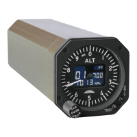
AD20 Standby Altimeter
Page 5 of 72
07-Sep-2009 Document No: AD-INSOP-800 Revision: 1.6
3.1.3.6 Hysteresis......................................................................................................................40
4 SECTION IV ..................................................................................................................................41
4.1 Installation................................................................................................................................41
4.1.1 General.............................................................................................................................. 41
4.1.2 Unpacking and Inspecting................................................................................................. 41
4.1.3 Pre and Post Installation Check........................................................................................ 41
4.1.4 Electrical Interface............................................................................................................. 41
4.1.4.1 Overview of electrical interface ..................................................................................... 41
4.1.4.2 Power Control (DC Primary) ......................................................................................... 41
4.1.4.3 Power Consumption ...................................................................................................... 41
4.1.4.4 Power Failure indication................................................................................................ 42
4.1.4.5 Groundings and Shielding............................................................................................. 42
4.1.4.5.1 Harness with shielded power wires, RF Susceptibility Cat. [YY] ........................... 42
4.1.4.5.2 Harness with unshielded power wires, RF Susceptibility Cat. [WW] ..................... 43
4.1.5 Electrical connector........................................................................................................... 44
4.1.5.1 Pin Assignments............................................................................................................ 44
4.1.5.2 Wiring Diagram (shielded power wires, RF Susc. Cat. [YY]) ....................................... 46
4.1.5.3 Wiring Diagram (unshielded power wires, RF Susc. Cat. [WW]) ................................. 47
4.1.6 Digital Data Interface......................................................................................................... 48
4.1.6.1 ARINC 429 (optional) .................................................................................................... 48
4.1.6.1.1 ARINC 429 Data bus Interface ............................................................................... 48
4.1.6.1.2 ARINC 429 BIT Rate............................................................................................... 48
4.1.6.1.3 ARINC Label Formats ............................................................................................. 48
4.1.6.1.4 Label 203 (Pressure Altitude) ................................................................................. 49
4.1.6.1.5 Label 204 (Baro corrected altitude #1) ................................................................... 50
4.1.6.1.6 Label 217 (Static Pressure ) ................................................................................... 51
4.1.6.1.7 Label 234 (Baro correction hPa #1)........................................................................ 52
4.1.6.1.8 Label 235 (Baro correction inHg #1)....................................................................... 53
4.1.6.1.9 Label 270 (Discrete word #1).................................................................................. 54
4.1.6.1.10 Label 350 (Maintenance word #1) (Provision) ..................................................... 55
4.1.6.2 Discrete I/O’s ................................................................................................................. 56
4.1.6.2.1 Discrete Inputs ........................................................................................................ 56
4.1.6.2.2 Discrete Input Functions ......................................................................................... 56
4.1.6.2.3 Aircraft Type Selection............................................................................................ 56
4.1.6.2.4 Discrete Outputs ..................................................................................................... 57
4.1.6.3 RS232 Serial Interface .................................................................................................. 57