P4
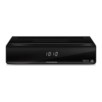
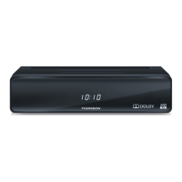
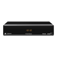
YOUR RECEIVER
1. 4 digits display: Indicates current time in STANDBY mode
Indicates current channel number or action in
OPERATING mode
2. IR sensor: Point your remote control towards this sensor.
3. Mode indicator: Red indicates that the receiver is in
STANDBY mode.
In OPERATING mode it is off.
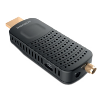
2.3 Rear Panel
Fig. 2
1. ANT IN To connect to your antenna for the reception of
broadcast signal.
2. USB Connector for USB devices.
3. TO TV To connect to the terrestrial antenna input of your
TV set.
4. IR Sensor To connect to extended IR sensor.
5. HDMI To connect your receiver with your TV set using a
HDMI cable.
6. Video Connector To connect your receiver with your TV set using a
cinch cable.
7. Audio R/L Connector To connect your receiver with your TV set using a
cinch cable.
8. TV SCART To connect your receiver with your TV set using a
SCART cable.
9. S/PDIF Coaxial To connect your receiver to a digital audio amplifier.
10. Power Cord Your receiver requires a voltage of 220~240V
AC (Auto-selectable), 50/60Hz ±5%. Check the
local power specification before connecting your
receiver to the wall outlet.
2.4 Remote Control
Fig. 3
1. q Turns the receiver On/Standby
2. FAV Favourite group selection
3. TV/R Toggles between TV or RADIO mode
4. 0~9 Channel selection or value input
5. PG+/PG- Page up/down and 10 channels steps in channel
list mode
6. BACK Switches between the two last watched channels
7. Shows the current channel information
8. pq Menu Off: Change channel to previous/next.
Menu On: Moves the cursor up/down.
9. tu Menu Off: Increases/decreases the volume level.
Menu On: Moves the cursor left/right and change
settings for specific Menus