18
18
SIF5600 - Manual - 03 - 2008
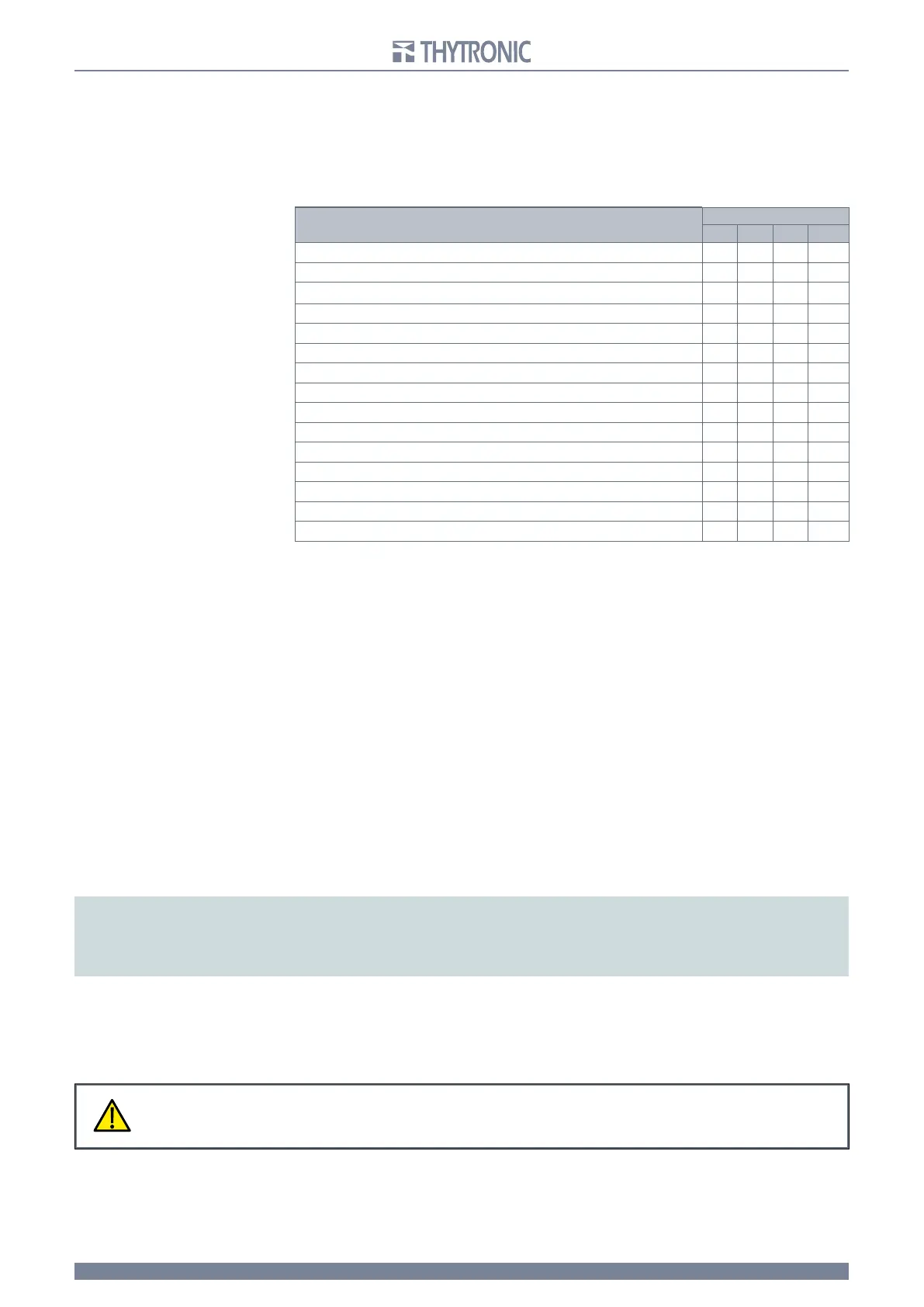
Output relay programming is equivalent to the following matrix
By way of example, one possible output relay selection matrix configuration is shown, typical for
applications conforming to the
ENEL DK5600 specification:
- tripping of I>, I>> and IE> functions (Trip I>, Trip I>>,Trip IE>) associated with output relay K1;
- breaker close command (Close 52) associated with K2;
- breaker open command (Open 52) associated with K3;
- start of I>, I>> and I
E> functions (Start I>, Start I>>, Start IE>) associated with output relay K4.
FUNCTIONS
RELAYS
K1 K2 K3 K4
Self-test
Trip I>
Trip I>>
Trip IE>
Trip IE>>
Start I>
Start I>>
Start IE>
Start IE>>
PW shorted
C
B fail
PW break Blin1
Self test 52
Open 52
Close 52
In addition, each output relay may be independently programmed to have normally energized or de-
energized, manual or automatic reset (Latch or No-Latch) modes of operation. Output relays pro-
grammed for breaker self test and diagnostics (Self test 52) are normally automatically configured
as energized with automatic reset and are excluded from the menu options for other functions. Pro-
gramming and alteration of the configuration may be performed at any time, even with the relay in
operation.
Th
ere are a number of modes of operation, independently programmable for each output relay:
- in the case where a output relay is set to be normally de-energized (K1...4 DeEn), it is kept in the
resting state with input quantities corresponding to the non-trip condition;
-
in the case where a output relay is set to be normally energized (K1...4 En), it is kept powered up in
the operational state with input quantities corresponding to the non-trip condition;
- in the case where a output relay is set for self-testing, it is normally kept in the operative state and
is de-energized upon removal of the auxiliary voltage or in any case upon detection of any faults in
the protective device internal circuitry.
Normally, the state of output relays corresponding to protective device tripping is characterized by
automatic resetting when the input quantity anomalous condition has ceased (K1...4 NoLatch mode),
w
hile the front panel trip indications remain and must be reset by means of the RESET button. In any
case, it is possible to configure operation so that one or more of the output relays, like the indicator,
r
emains in the tripped condition (K1...K4 Latch mode) until the RESET button is pressed, or the same
command is given over the terminal block RS485 serial communication interface or the front panel
RS232 (ThySetter).
Note:
during programming (Set), for each relay, there are the following for combinations:
- DeEn-NoLatch (normally de-energized, automatic reset)
- DeEn-Latch (normally de-energized, trip stored)
- En-NoLatch (normally energized, automatic reset)
- En-Latch (normally energized, trip stored)
A timer tTR may be set within the range 0.01...1.00 s with a 0.01 s step for each output relay (tTR1...4),
having the role of setting a minimum trip condition dwell time for each output relay. Output relays
programmed
for manual reset may be reset by means of the RESET button on the front of the relay,
or by the same command given over the terminal block RS485 serial communication interface or the
front panel RS232 (ThySetter).
LED indicators
The following indicators may be found on the front panel:
- green ON LED, if on, indicating that the auxiliary power supply to the relay is correct, and if flashing,
indicating that the internal self-test function has detected an anomaly;
-
red 50-51 LED, if on, indicating the tripping of the first or second maximum overcurrent protective
device threshold assigned to at least one output relay; this LED should be reset manually;
CAUTION
It is advised to check whether the characteristics of the output relay output contacts are suited
to the type of breaker coil, in terms of nominal current, nominal voltage, closing power and
breaking power, by referring to the data in the Technical Characteristics.
CAUTION
It is advised to check whether the characteristics of the output relay output contacts are suited
to the type of breaker coil, in terms of nominal current, nominal voltage, closing power and
breaking power, by referring to the data in the Technical Characteristics.