42
42
SIF5600 - Manual - 03 - 2008
Block
Logic selectivity
This sub-menu includes the calibration parameters tB and tF concerning to the block circuits as well
as enabling the reception and/or output transmission of pulses for continuity checking of the pilot
wire.
Should more protective devices be connected to the block input circuit of the same protective device
upstream, then it is necessary that the emission of control pulses be enabled on a single protective
device.
Block submenu example:
tF enable
On Enabling timer tF
tF 0.250 s Setting the deactivation delay time for both output circuits
tB enable On Enabling timer tB
tB 0,300 s Setting the block input circuit maximum activation time
Pulse Blin1 Off Disabling reception of control pulses over the block input circuit
Pulse Blout Off Disabling transmission of control pulses over both block output circuits
Settings for tF, tB and programming the output control pulse are common to all possible block func-
tions.
T
he Pulse Blout function, concerning the block output signal, must be set to On, in order to activate
output of pilot wire continuity control pulses.
Should the reception of control pulses over Blin1 (Pulse Blin1) be enabled, then it is possible to set
the control window within which pulse reception is controlled; the selectable values are 0.05, 0.1, 1,
10 or 30 s.
To
disable reception of control pulses over inputs Blin1 it is necessary to set the relevant parameter
to Off (e.g.: Pulse Blin1 Off)
Output pulses must be enabled on the SIF5600 digital protection relay installed downstream, in the
case where it is intended to use the pilot wire control function; it is important that the control window
settings are identical to the Blin1 Pulse settings on the SIF5600 relay located upstream.
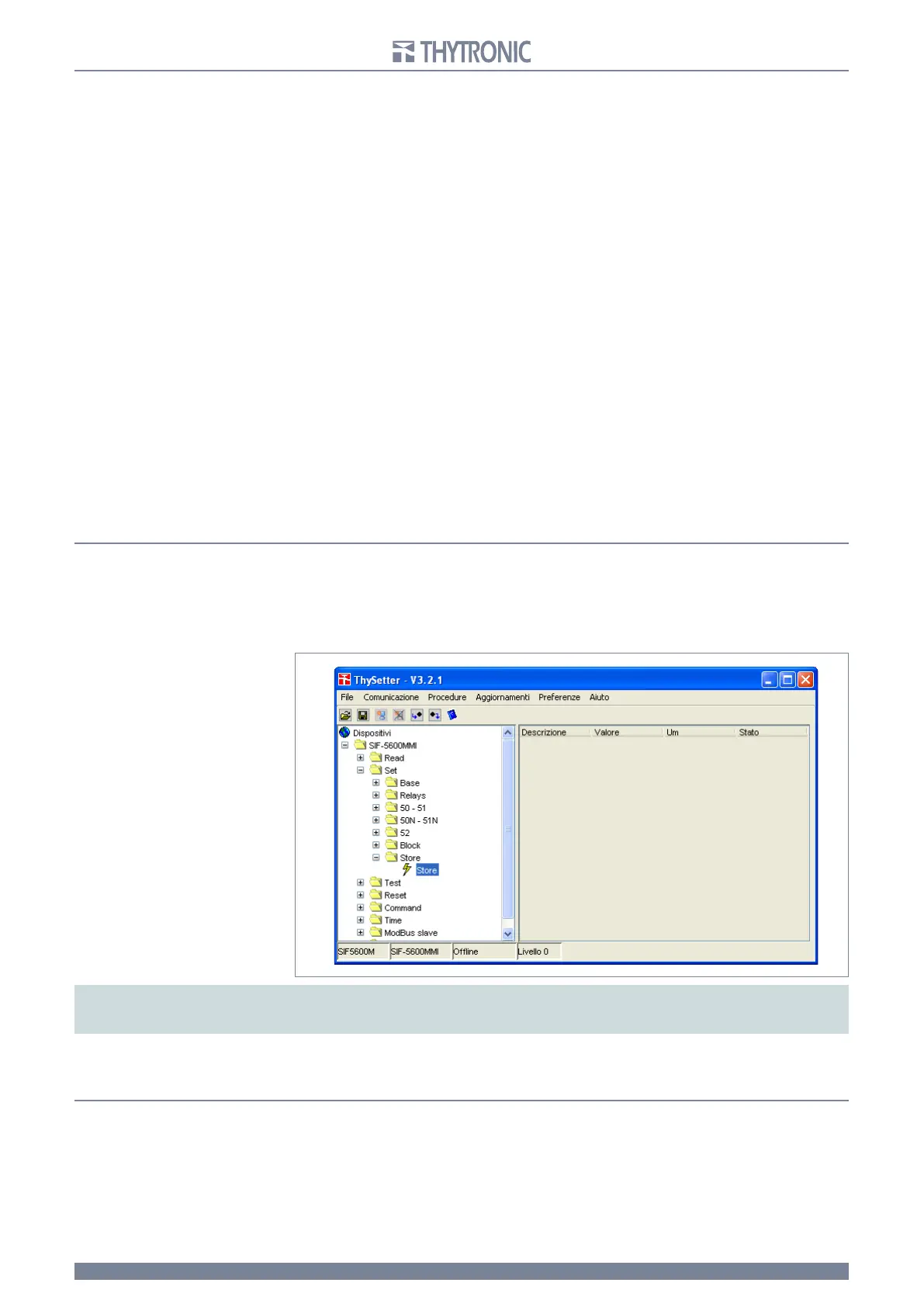
Store
The Store command allows the settings being modified to be recorded permanently in the SIF5600
relay EEPROM memory and hence to be made definitively operative.
To execute the Store command, it is necessary to position the mouse cursor over the desired mes-
sage and double click, or expand the menu until the yellow coloured symbol appears and activate
“send the command” by clicking the box which opens after right clicking with the mouse.
Note: for all modifications, the new settings only become definitive with the “Store” command located in the Store sub-menu.
To go back to the previous settings, it is necessary to abort any modifications by responding negatively to the save request which appears while
exiting the program.
Unsaved modifications (made prior to use of the “Store” command) are highlighted by the presence
of a red background for those modified parameters and folders (menu levels) containing modified
parameters.
TEST ROUTINES (Test)
Activating the test sequence results in the input of a dummy signal into the processing circuit stages,
which causes tripping of the selected protective function and hence the switching of the output relay
and the illumination of the red indicator L
ED.
The green ON LED flashes for the entire duration of the test (with or without output relay switching).
This test does not include the current signal input transformers, but may be usefully considered in an
appropriate periodic testing programme.
Testing
may or may not cause switching of the output relays; in the former case (Test I>TR) it causes
tripping of the system protective breakers: hence the test is automatically extended to the entire
 Loading...


