50
50
SIF5600 - Manual - 03 - 2008
7 A P P L I C A T I O N N O T E S
7.1 LOGIC SELECTIVITY
The block function may be applied to short circuit I>> and ground fault IE>> functions. It must be
arranged in relation to the established coordination criterion; the two circuits, block input (BLOCK
IN) and block output (BLOCK OUT), are completely independent from one another and must be pro-
grammed separately.
Block functions may be programmed from within the SIF5600 relay 50-51 and 50N-51N function sub-
menus.
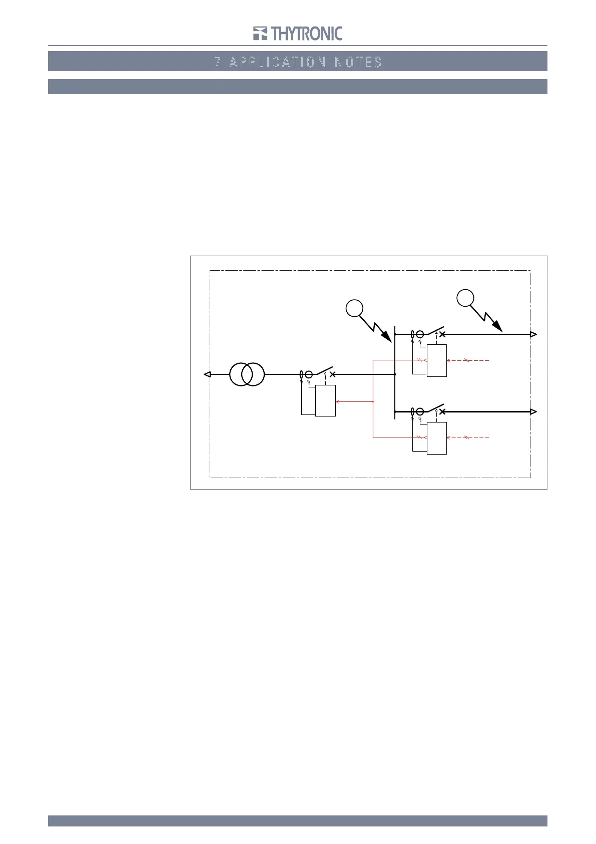
In the example reported below, the block function is enabled on the short-circuit function; it repre-
sents the typical application of an accelerated logic system, where two or more protective devices,
operating in cascade mode, are programmed with minimum times using the block on the I>> func-
tion.
T
he figure shows the case where protective device B, in the case of a fault in the point indicated (2),
sends a block signal to the upstream protective device A. Due to the fault in the point indicated, both
protective devices are started, since both detect the fault current.
At the time of starting, protective device B sends the block signal to protective device A, resetting the
corresponding trip timer and putting it in the blocked state. Since protective device B is not blocked
by any downstream protective devices, upon expiry of its own trip time, it commands the opening of
the corresponding breaker, thus selectively isolating the fault.
In the case of a fault in the point indicated (1) rather than (2), the breaker opening command will be
sent by protective device A, since it is not blocked by any signals originating from the relays located
downstream.
T
he allocation of calibration parameters occurs in a manner very similar to that described above for
the other protective functions; it is necessary to enter into the 50-51 sub-menu, alter the settings in
accordance with the desired values and activate the input and output block function
For example, settings for protective devices A and B may be as follows:
- protective device A
I>> indep
4.5 In
t>> indep 0.10 s
Blin I>> On
Blout I>> Off
- protective device B
I>> indep
4.0 In
t>> indep 0.10 s
Blin I>> Off
Blout I>> On
The selection of trip times (0.10s for both protective devices A and B) ensures the correct operation
of the accelerated logic system, considering the transmission and reception delays of the blocking
signal
and the further delays in fault detection introduced by phenomena of non-linearity (e.g.: CT
saturation).
Adjusting tF, tB, enabling the block input circuit by pilot wire and programming the output control
impulse are common to both 50 and 50N block functions): these are available from inside the Block
sub-menu.
T
he Pulse Blout function, relating to the block output signal, must be set to On, to activate output of
the self-check control impulses to check pilot wire continuity.
BLOUT1
TRIP I>>
BLOUT1
BLIN1
BLIN1
50N
50
TRIP I>>
50N
50
TRIP I>>
50N
50
SIF5600
A
B
C
SIF5600
BLIN1
SIF5600
1
2
 Loading...


