20
20
SIF5600 - Manual - 03 - 2008
Logic selectivity
One block input circuit (Blin1) and two block output circuits (Blout1 and Blout2) are available for the
pilot wire accelerated logic.
T
he block circuits do not require separate auxiliary power, since their power is derived from the
SIF5600 relay.
Assignment of the input circuit Blin1 to the maximum overcurrent protection second threshold I>>
and/or
the residual maximum overcurrent protective device second threshold IE>> may be pro-
grammed independently as follows:
- assignment of the maximum overcurrent protection second threshold I>> to input circuit Blin1
Blin I>> On
- assignment of the maximum residual current protection second threshold IE>> to input circuit
Blin1 Blin IE>> On
Analogously, assignment of the two output circuits Blout1 and Blout2 to the maximum overcurrent
protection second threshold I>> and/or the residual maximum overcurrent protective device second
threshold I
E>> may be programmed independently as follows:
- assignment of the maximum overcurrent protection second threshold I >> to output circuits Blout1
and Blout2
Blout I>> On
- assignment of the maximum residual current protection second threshold IE >> to input circuits
Blout1 and Blout2 Blout IE>> On
For any given threshold (I>> or IE>>), the logic state of the two output circuits, tripping and threshold
status, are conditioned by the start logic state of the threshold itself and the logic state of the input
circuit, as shown in the following table which summarizes the operation of the relay accelerated
logic.
START
THRESHOLD
(Start)
INPUT
Blin1
OUTPUT
Blout1
OUTPUT
Blout2
TRIP
THRESHOLD
(Trip)
STATE
THRESHOLD
0 0 0 0 0 REST
0 1 0 0 0 REST
1 0 1 1 1 TRIP
1 1 1 1 0 B
LOCK
The input and output circuits are understood as having logic state 0 (deactivation) or logic state 1
(activation) respectively in the absence or presence of signals over the pilot wires connected to
them.
Output circuits Blout1 and Blout2 are only activated at the start of the threshold associated with
them.
In the absence of start, the protective device stays in the resting state.
T
he protective device may trip and switch the programmed output relays only if the threshold is
started and exceeded for the entire duration of the trip time set and if the input circuit Blin1 is not
active; instead, with the threshold started and input circuit Blin1 active, the protective device is in
the blocked state and hence does not switch any of the output relays (in the blocked state, the trip
timer is reset and maintained at zero).
With the aim of increasing the reliability of the accelerated logic system, the SIF5600 protection relay
additionally makes use of the periodic pilot wire continuity check function and the pilot wire short
circuit and breaker failure backup functions.
T
he periodic pilot wire continuity check function checks for the reception of impulses, sent from the
output circuitry of another relay, to the input circuit Blin1; the impulses are of such a duration as not
to result in the blocking of the protective devices.
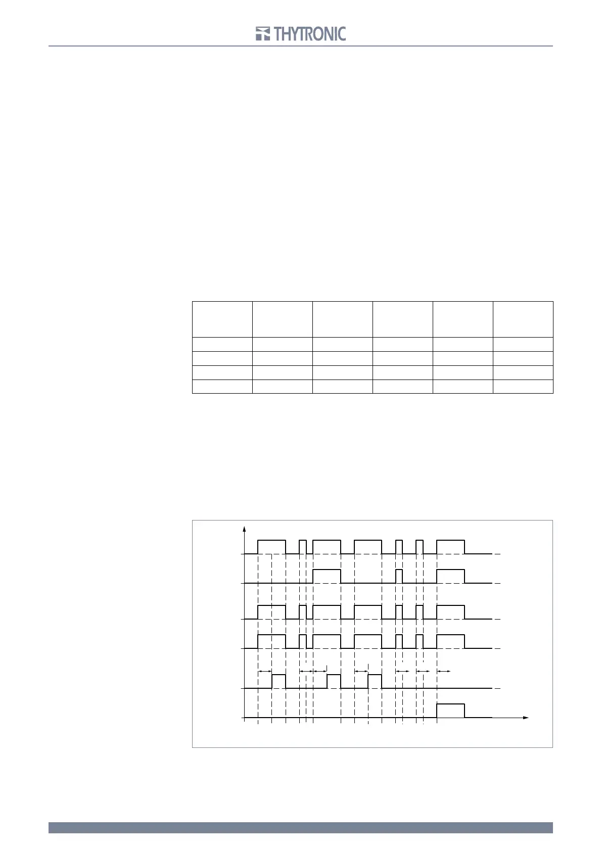
LOGIC STATE DIAGRAM CONCERNING THE ACCELERATED LOGIC
BlocK
Trip
Blout2
Blout1
Blin1
Start
t>>
t
t>>t>>t>>
t>>t>>
t>>
TX@FOBJ