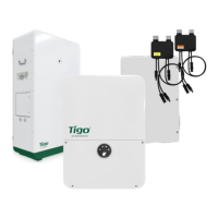
The EI Inverter – Box Contents
EI Residential Solar Solution US Installation Manual | www.tigoenergy.com | Help Center 7
The EI Inverter
This section includes:
• Box Contents
• Enclosure Overview
• Mounting
• Communications Connections
• Power Connections
• Rapid Shutdown – E-Stop Switch
For detailed specifications, download the EI Inverter data sheet from the tigoenergy.com
Downloads page.
Box Contents
The EI Inverter box includes:
• EI Inverter
• Quick Start Guide
• Mounting bracket
• Tigo Access Point (TAP)
• Rapid Shutdown label
• E-Stop rapid shutdown switch
• DC wire ferrules (3.8kW: 12, 7.6kW:16, 11.4kW:20)
• AC wire ferrules (5)
• 2-pin plug for 12V ATS communications connection (not included with all models)
• 3-pin plug for RS-485 ATS communications connection
• 6-pin plug for ATS communications connection (installed on the EI ATS)
• Grounding ring terminal
• Hex-head self-tapping screws (inverter mounting, 5)
• Philips-head screw (E-Stop mounting, 4)
• White wall anchors (inverter, 5)
• Green wall anchors (E-Stop, 4)
• WiFi antenna
• Cellular antenna (only with cell-enabled models)
• .875in OD knockout for 1/2in plug with nut
• 1.375” OD knockout for 1in plug (2)
• 1.375” OD knockout for 1in plug with nut (2)
Enclosure Overview
MAC ID
A label with the inverter’s MAC ID and a tigoenergy.com
QR code is located on the left side below the specifications
label.
 Loading...