The EI Inverter – E-Stop Switch for Rapid Shutdown
EI Residential Solar Solution US Installation Manual | www.tigoenergy.com | Help Center 19
E-Stop Switch for Rapid Shutdown
Together, the Tigo EI Inverter and TS4-A-F/O PV MPLE enable a Photovoltaic Rapid Shutdown
System (PVRSS) as defined by NFPA 70, National Electrical Code (NEC).
• If grid power fails in a grid-tie system, the EI solution automatically shuts down each PV
module’s output and disconnects any marginal PV power to the grid.
A manual rapid shutdown switch is optional.
• If grid power fails in a system that uses a battery, PV output is unaffected, and the EI
solution disconnects any PV or battery power to the grid.
A manual rapid shutdown switch is mandatory.
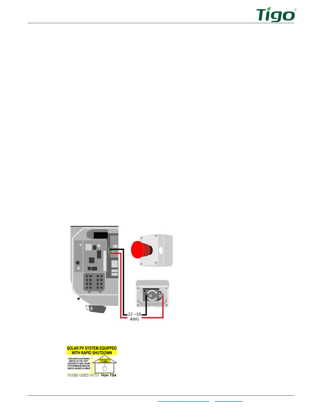
To install the E-Stop rapid shutdown switch:
1. Mount the E-Stop switch within 1m/3ft of the inverter or service entrance outside the
residence.
It must be clearly visible and accessible to first responders and maintenance workers.
2. At the inverter, route two 22 – 18 AWG conductors through the left
COM
knockout.
3. Remove the 3-pin connector from the CN14 port.
4. At the inverter, connect the conductors to the 3-pin connector in positions
1
and
3
(position
2
is open). Polarity is not important.
5. Route the conductors to the E-Stop switch and connect them to the two E-Stop
terminals.
6. Affix the rapid shutdown label within 1m/3ft of the E-Stop switch.
 Loading...