Pre-Installation – Location
EI Residential Solar Solution US Installation Manual | www.tigoenergy.com | Help Center 4
Pre-Installation
Location
EI enclosures are NEMA 4/IP65 rated for indoor and outdoor exposure. To optimize
performance and extend service, locate the enclosures:
• In a well-ventilated, easily accessible location.
• On a flat surface against a solid wall with ≤15
° tilt.
• Sheltered from direct sunlight and excessive moisture. The ambient temperature is
ideally below 50°C.
• Away from antennas or other sources of electromechanical interference.
• Above potential flooding.
Component Layout
Follow these guidelines when planning how to mount components:
Inverter
• As close as possible to the main service panel to minimize AC voltage drop.
• At least 3m/36in above the ground.
• With a minimum 300mm (12in) clearance around the top and sides.
E-Stop rapid shutdown switch
• Adjacent the inverter and service entrance.
• Clearly visible and accessible to first responders and maintenance workers.
ATS
• Adjacent the inverter and service entrance.
• With a minimum 300mm (12in) clearance around all sides.
Battery
• On level ground.
• With a minimum 914mm (36in) side and top clearance from other system
enclosures/objects.
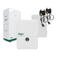
Component Dimensions
Plan on accommodating the following approximate dimensions (width/height/depth):
400 x 570 x 170mm (15.75 x 22 x 6.7in)
400 x 640 x 190mm (15.75 x 25.2 x 7.5in)
450 x 550 x 180mm (17.7 x 21.7 x 7.1in)
650 x 1160 x 320mm (25.6 x 45.7 x 12.6in)