The EI Battery – Place and Prepare
EI Residential Solar Solution US Installation Manual | www.tigoenergy.com | Help Center 37
5. Place one battery module in the upper section and two modules in the lower section
with the power terminals on the right side.
6. Secure the modules with the brackets attached to the enclosure.
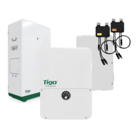
7. In the upper section, connect the cables labeled
PCS
,
Upper bat Link-Out, Upper bat+
(red), and
Upper BAT–
(black) to their respective terminals.
8. Insert an RJ45 terminator in the
Link In
terminal.
The accessory bag in the battery module package includes two terminators.
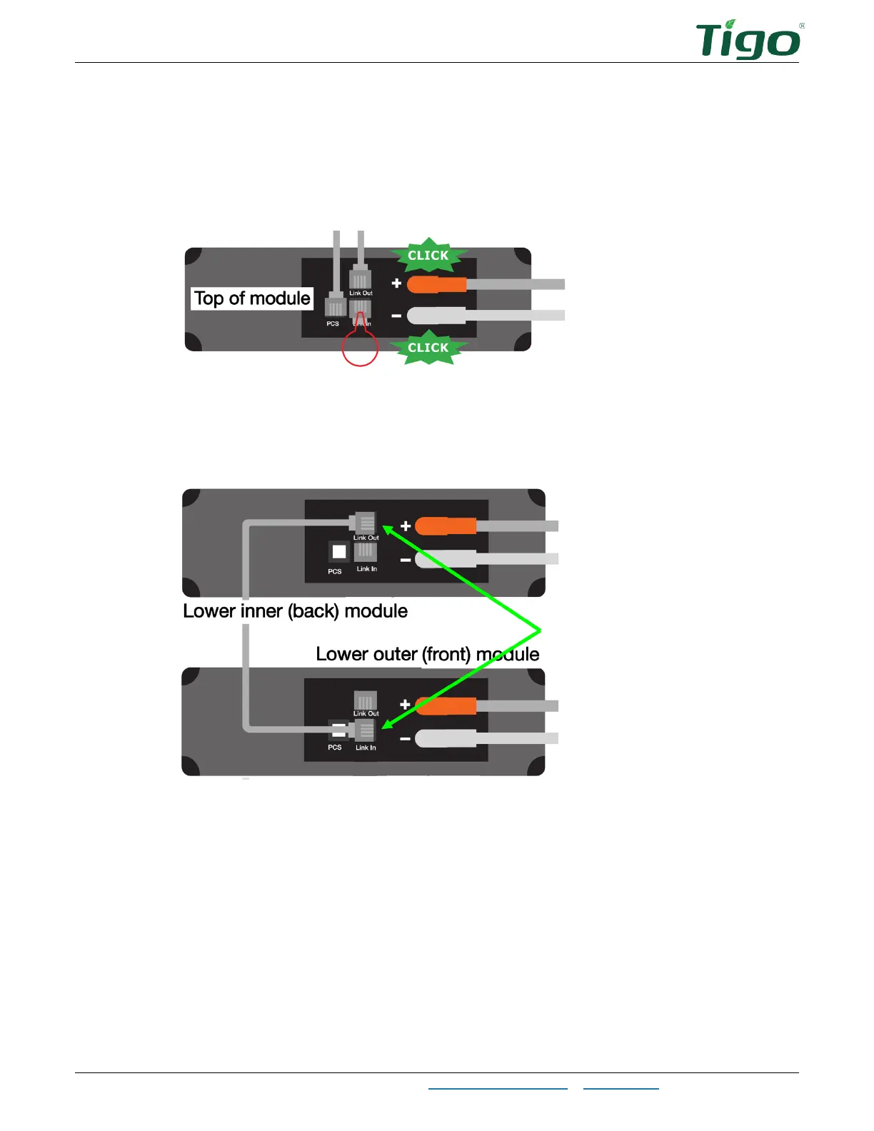
9. In the lower section, connect the loose
Lower inner bat Link-Out
cable to the inner
(back) module
Link Out
terminal and the outer (front) module
Link In
terminal.
10. Connect the other cables according to their labels.