Description
Product 25
TK Elevator
BA, TW45 | 6231003860 | 03/2023
▪ Driving gear in emergency brake NBS version (bearing bracket NBS, brake
flange NBS for fitting the brake)
▪ Traction sheave / worm wheel shaft NBS (including components for seal-
ing)
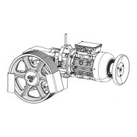
The braking device is located on the machine side opposite the traction
sheave and directly affects the traction sheave shaft.
A certificate with respect to the calculation of the traction sheave shaft for
the machine TW45C with emergency brake system (NBS) shall be enclosed
with the technical documentation.
The emergency brake is activated via a separate control unit including ter-
minal box and connecting lines as well as an additional safety switch at the
overspeed governor (TK Aufzugswerke GmbH) to activate the facility in the
event of overspeed (not for ISIS1 version).
For the version in the machine room, the emergency brake is released manu-
ally (e.g. emergency rescue in the event of a power failure) via screws that are
screwed into the brake in the event of triggering, thus releasing the brake/
armature base plate of the disc brake. During normal operation, the screws
and a socket wrench are kept in the guard plate of the brake.
For installation of the manual release screw, a minimum distance of 100 mm
is to be set between the emergency brake and the adjoining wall of the ma-
chine room or similar.
Later fitting of the emergency brake, NBS, on existing machines is not pos-
sible.
3.3.6 Version with earthquake safeguard complying with
EN81-77
The optional version of the rope guard complying with EN81-77 enables com-
pliance with the requirements for protection devices in earthquake regions up
to earthquake category 1 as standard.
The rope guard fitted as standard is replaced with the modified rope guard
which, in the event of an earthquake, prevents the ropes from leaving the
groove of the traction sheave. Attention should be paid to ensuring that the
rope guard is installed in accordance with the installation instructions.
The rope guard complying with EN81-77 is standardised for the traction
sheave diameters 440 / 520 / 590. The rope guard is designed in such a way
that all standard gaps between the ropes on the rope departure can be
covered with the TW45B O SR and TW45B M SR base frames.
3.3.7 Version for machine location in the shaft pit for ISIS1
This version is intended for TKE-NA. The machine is located in the shaft pit
with upward vertical rope pull and is intended for a range of performance
from 2100 lbs/100 fpm to 3000 lbs/200 fpm, with traction sheave 10.5 in
(D267 mm) and rope attachment 2:1 in each case.
As gear ratios, the versions 40:3 and 32:3 are intended. The versions EMOD
5.5 / 7.5 and 11 kW in voltage interchangeable version 230 / 460 V are de-
ployed as motors.