Installation
Electrical connection 59
TK Elevator
BA, TW45 | 6231003860 | 03/2023
9. Tighten the cap nut with the recommended torque in accordance with
manufacturer documentation
Chap.10.2P.75.
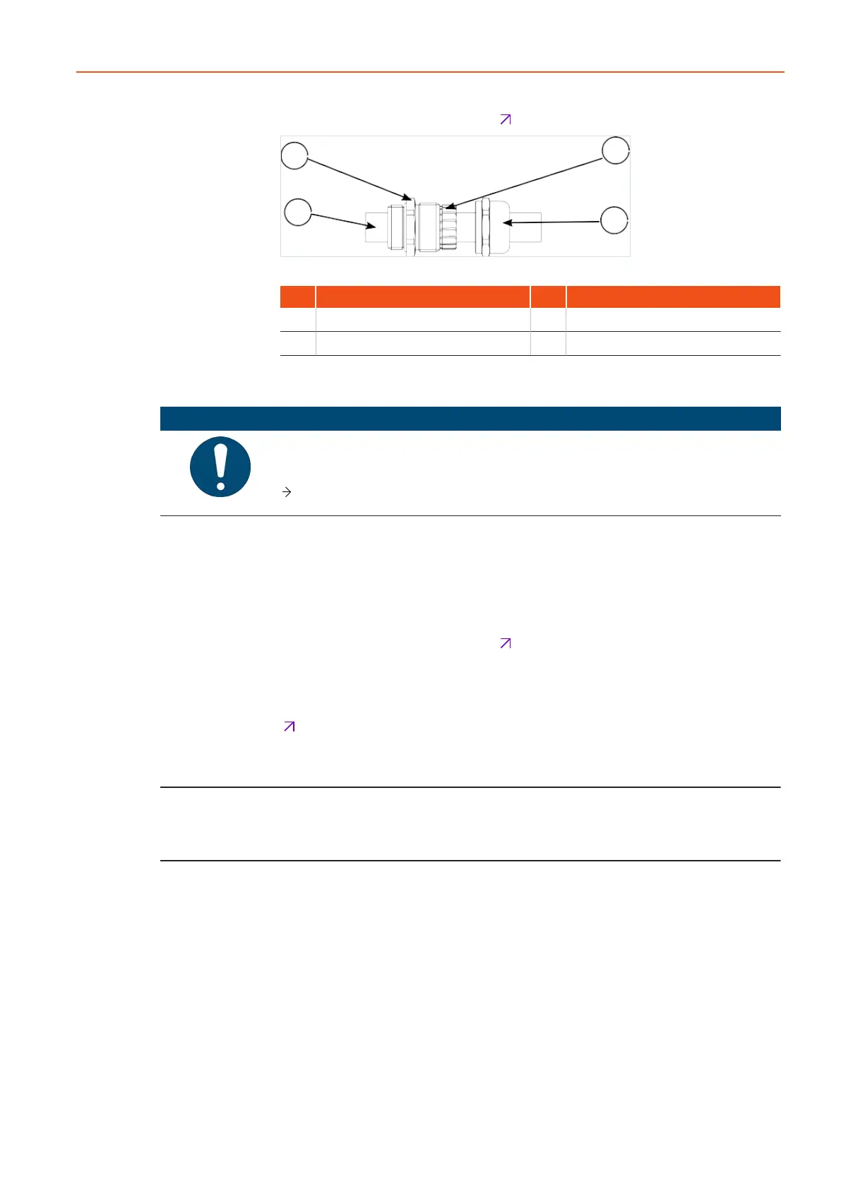
Fig.30 ATR_2_21_0055_0
Item Designation Item Designation
1 Cable with shielding braid 2 Lock nut
3 Lamellar insert 4 Cap nut
6.7.3 Connecting the posistor
NOTICE
Overvoltage at the measuring device!
Defective measuring device.
Do not apply a voltage greater than 2.5 V.
A triggering device (motor protection device) is required for evaluation of the
posistor temperature sensor installed in the motor.
1. Strip the insulation from the connection line.
2. Connect both wires in accordance with the terminal connecting plan.
3. Tighten the cap nut with the recommended torque in accordance with
manufacturer documentation
Chap.10P.75.
6.7.4 Connecting the brake
Connect the brake (coil and microswitch) via the motor terminal box
Chap.6.7.1P.57.
Emergency brake NBS (optional)
If the emergency brake system is fitted, a description with all the details regard-
ing connection and operation of the emergency brake can be found in the sep-
arately enclosed operating manual for the emergency brake system, NBS.