Installation
Rope pulley on the machine base frame 55
TK Elevator
BA, TW45 | 6231003860 | 03/2023
The rope guards on the rope pulley are to be mounted according to the same
specifications.
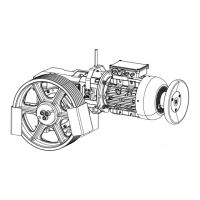
6.5 Rope pulley on the machine base frame
All rope guards can be used for the ASL range of .
1. Mount the rope guards on the machine base frame.
2. Set the rope guard by pivoting or remounting in such a way that the clear-
ance between the rope and hoop guard does not exceed a maximum of 2
mm over the entire width of the traction sheave.
3. Set the rope guard with a maximum angle of 15° at the rope entry point
and rope departure point.
If the angle between the rope entry point and rope departure point is
greater than 90°,
fit a third rope guard if the angle between the rope entry point and
rope departure point is greater than 90°.
The angle between all rope guards must be less than 90°.
4. After alignment, tighten the securing bolts of the rope guards with the
prescribed tightening torque.
5. With inclined pulling, adapt the location of the rope guard carrier by re-
mounting the changed rope pull direction.
6.6 Shift protection on the machine base frame
The fastening materials (Hilti HST M16/25 or Fischer M16/25 FAZ II) are in-
cluded in the scope of supply and must be attached to the unfinished floor.
Comply with the installation instructions of the manufacturer.
In locations where the distance to the wall is < 250 mm, the standard shift pro-
tection devices must be replaced by devices for low wall clearances.
The shift protection is configured for the following machine insulations:
▪ Insulation elements without underlay for machine room without floor
pavement
▪ Insulation elements with underlay for machine room with floor pavement
(≤ 60 mm height); support made from Multiplex laminated wood
140x140x80 mm.